FAA-H-8083-25C · Source PDF page 183
Aircraft Systems
N Indicator · PHAK page 7-23
Searchable transcription
Turboprop and turboshaft engines are designed to produce temperatures also results in decreased thrust. While both
torque for driving a propeller. Torquemeters are calibrated turbine and reciprocating powered engines are affected to
in percentage units, foot-pounds, or psi. some degree by high relative humidity, turbine engines will
experience a negligible loss of thrust, while reciprocating
N Indicator engines a significant loss of brake horsepower.
1
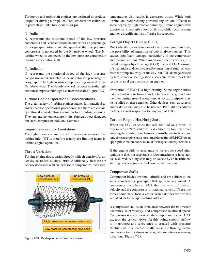
N represents the rotational speed of the low pressure
1
compressor and is presented on the indicator as a percentage Foreign Object Damage (FOD)
of design rpm. After start, the speed of the low pressure Due to the design and function of a turbine engine’s air inlet,
compressor is governed by the N turbine wheel. The N the possibility of ingestion of debris always exists. This
1 1
turbine wheel is connected to the low pressure compressor causes significant damage, particularly to the compressor
through a concentric shaft. and turbine sections. When ingestion of debris occurs, it is
called foreign object damage (FOD). Typical FOD consists
N Indicator of small nicks and dents caused by ingestion of small objects
2
N represents the rotational speed of the high pressure from the ramp, taxiway, or runway, but FOD damage caused
2
compressor and is presented on the indicator as a percentage of by bird strikes or ice ingestion also occur. Sometimes FOD
design rpm. The high pressure compressor is governed by the results in total destruction of an engine.
N turbine wheel. The N turbine wheel is connected to the high
2 2
pressure compressor through a concentric shaft. [Figure 7-27] Prevention of FOD is a high priority. Some engine inlets
have a tendency to form a vortex between the ground and
the inlet during ground operations. A vortex dissipater may
Turbine Engine Operational Considerations
The great variety of turbine engines makes it impractical to be installed on these engines. Other devices, such as screens
cover specific operational procedures, but there are certain and/or deflectors, may also be utilized. Preflight procedures
operational considerations common to all turbine engines. include a visual inspection for any sign of FOD.
They are engine temperature limits, foreign object damage,
hot start, compressor stall, and flameout. Turbine Engine Hot/Hung Start
When the EGT exceeds the safe limit of an aircraft, it
Engine Temperature Limitations experiences a “hot start.” This is caused by too much fuel
The highest temperature in any turbine engine occurs at the entering the combustion chamber or insufficient turbine rpm.
turbine inlet. TIT is therefore usually the limiting factor in Any time an engine has a hot start, refer to the AFM/POH or an
turbine engine operation. appropriate maintenance manual for inspection requirements.
If the engine fails to accelerate to the proper speed after
Thrust Variations
ignition or does not accelerate to idle rpm, a hung or false start
Turbine engine thrust varies directly with air density. As air
has occurred. A hung start may be caused by an insufficient
density decreases, so does thrust. Additionally, because air
starting power source or fuel control malfunction.
density decreases with an increase in temperature, increased
Compressor Stalls
Low pressure High pressure Compressor blades are small airfoils and are subject to the
compressor (N ) compressor (N )
1 2 same aerodynamic principles that apply to any airfoil. A
compressor blade has an AOA that is a result of inlet air
velocity and the compressor’s rotational velocity. These two
forces combine to form a vector, which defines the airfoil’s
actual AOA to the approaching inlet air.
A compressor stall is an imbalance between the two vector
quantities, inlet velocity, and compressor rotational speed.
Compressor stalls occur when the compressor blades’ AOA
exceeds the critical AOA. At this point, smooth airflow
High pressure compressor drive shaft
is interrupted and turbulence is created with pressure
fluctuations. Compressor stalls cause air flowing in the
Low pressure compressor drive shaft
compressor to slow down and stagnate, sometimes reversing
direction. [Figure 7-28]
Figure 7-27. Dual-spool axial-flow compressor.
7-23