FAA-H-8083-25C · Source PDF page 352
Airport Operations
In-Runway Lighting · PHAK page 14-18
Searchable transcription
Above glidepath
On glidepath
Below glidepath
14-18
P
nit
a sl
e u ti h w
g
dy
St
h
e
i
a te
Steady
w red
d
g
re
n
Slightly below glidepath P
ulsati
Threshold
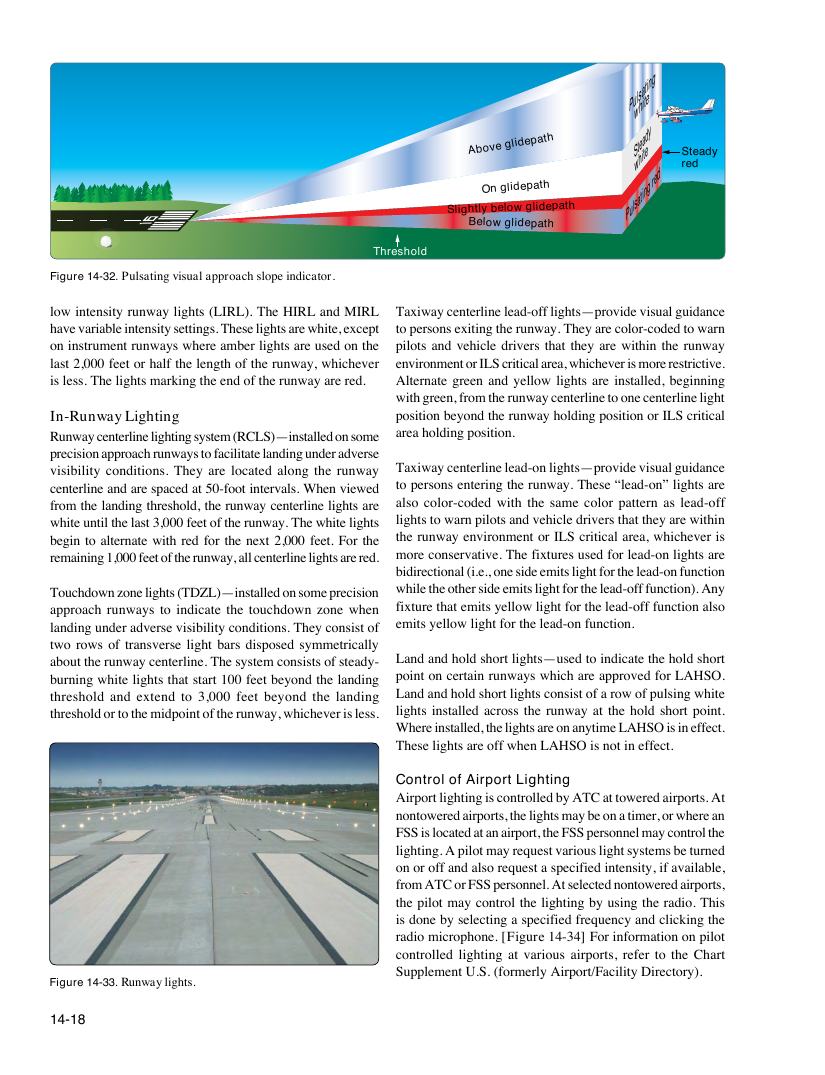
Figure 14-32. Pulsating visual approach slope indicator.
low intensity runway lights (LIRL). The HIRL and MIRL Taxiway centerline lead-off lights—provide visual guidance
have variable intensity settings. These lights are white, except to persons exiting the runway. They are color-coded to warn
on instrument runways where amber lights are used on the pilots and vehicle drivers that they are within the runway
last 2,000 feet or half the length of the runway, whichever environment or ILS critical area, whichever is more restrictive.
is less. The lights marking the end of the runway are red. Alternate green and yellow lights are installed, beginning
with green, from the runway centerline to one centerline light
In-Runway Lighting position beyond the runway holding position or ILS critical
Runway centerline lighting system (RCLS)—installed on some area holding position.
precision approach runways to facilitate landing under adverse
visibility conditions. They are located along the runway Taxiway centerline lead-on lights—provide visual guidance
centerline and are spaced at 50-foot intervals. When viewed to persons entering the runway. These “lead-on” lights are
from the landing threshold, the runway centerline lights are also color-coded with the same color pattern as lead-off
white until the last 3,000 feet of the runway. The white lights lights to warn pilots and vehicle drivers that they are within
begin to alternate with red for the next 2,000 feet. For the the runway environment or ILS critical area, whichever is
remaining 1,000 feet of the runway, all centerline lights are red. more conservative. The fixtures used for lead-on lights are
bidirectional (i.e., one side emits light for the lead-on function
Touchdown zone lights (TDZL)—installed on some precision while the other side emits light for the lead-off function). Any
approach runways to indicate the touchdown zone when fixture that emits yellow light for the lead-off function also
landing under adverse visibility conditions. They consist of emits yellow light for the lead-on function.
two rows of transverse light bars disposed symmetrically
about the runway centerline. The system consists of steady- Land and hold short lights—used to indicate the hold short
burning white lights that start 100 feet beyond the landing point on certain runways which are approved for LAHSO.
threshold and extend to 3,000 feet beyond the landing Land and hold short lights consist of a row of pulsing white
threshold or to the midpoint of the runway, whichever is less. lights installed across the runway at the hold short point.
Where installed, the lights are on anytime LAHSO is in effect.
These lights are off when LAHSO is not in effect.
Control of Airport Lighting
Airport lighting is controlled by ATC at towered airports. At
nontowered airports, the lights may be on a timer, or where an
FSS is located at an airport, the FSS personnel may control the
lighting. A pilot may request various light systems be turned
on or off and also request a specified intensity, if available,
from ATC or FSS personnel. At selected nontowered airports,
the pilot may control the lighting by using the radio. This
is done by selecting a specified frequency and clicking the
radio microphone. [Figure 14-34] For information on pilot
controlled lighting at various airports, refer to the Chart
Supplement U.S. (formerly Airport/Facility Directory).
Figure 14-33. Runway lights.