FAA-H-8083-25C · Source PDF page 412
Navigation
OBS · PHAK page 16-25
Searchable transcription
S 21 5 1 2 4
2
1
3 0 6
3 3 3
Figure 16-31. Radio magnetic indicator.
16-25
W
7
30 33 N 3
6 30
33 3
6
W
HDG 33 3 O 42 BS 12 S F 5 R 1 OM21 E 42 I2 5I 2I 30 6
42
I2 5I
2I
8
A D F E A D F W 30 33 N 3 E 6 6 33 3 6 I2
O
42
BS 12 S
F
5
R
1
OM21 03
42 I2
5I
N
0 N 3 6
E
NAV NAV 30 33 3 6
18
03 33
W FROM 51
12
42 I2 5I 2I OBS 42 12 S
33 N 3
30 TO 6
W 5
E
O
42
BS 12 S 51
21
W
30 33 N TO 3 6 30 33 3 6
O
42
BS 12 S 51 21
E 42
I2 5I
2I 4
W 30 33 N TO 3 6 30 33 3 6
O
42
BS 12 S 51
21
E 42
I2 5I
2I
3
3
33 6
30
2I
42I2 5I
33 N 3 2
30 TO
6
W
E
O
42
BS 12 S 51
21
W 30 33 N TO 3 6 30 33 3 6 1
O
42
BS 12 S 51
21
E 42
I2 5I 2I
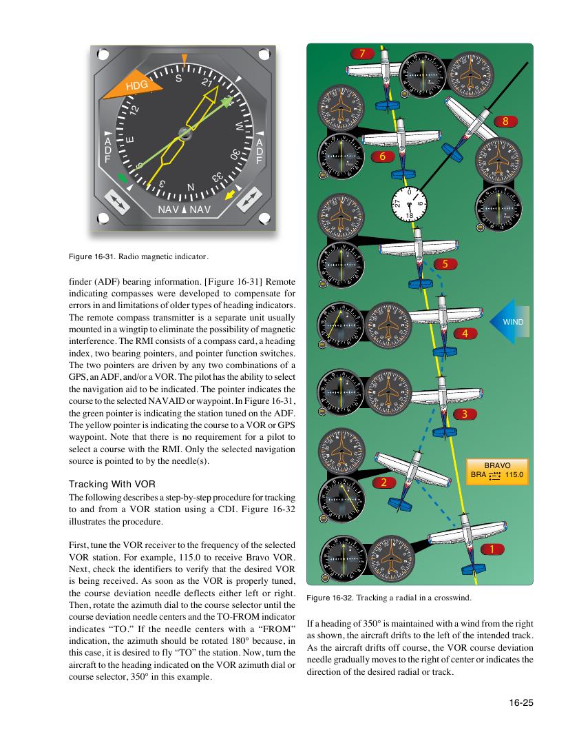
Figure 16-32. Tracking a radial in a crosswind.
72 6
finder (ADF) bearing information. [Figure 16-31] Remote
indicating compasses were developed to compensate for
errors in and limitations of older types of heading indicators.
The remote compass transmitter is a separate unit usually
WIND
mounted in a wingtip to eliminate the possibility of magnetic
interference. The RMI consists of a compass card, a heading
index, two bearing pointers, and pointer function switches.
The two pointers are driven by any two combinations of a
GPS, an ADF, and/or a VOR. The pilot has the ability to select the navigation aid to be indicated. The pointer indicates the
course to the selected NAVAID or waypoint. In Figure 16-31,
the green pointer is indicating the station tuned on the ADF.
The yellow pointer is indicating the course to a VOR or GPS
waypoint. Note that there is no requirement for a pilot to
select a course with the RMI. Only the selected navigation
source is pointed to by the needle(s).
BRAVO
BRA 115.0
Tracking With VOR
The following describes a step-by-step procedure for tracking
to and from a VOR station using a CDI. Figure 16-32
illustrates the procedure.
First, tune the VOR receiver to the frequency of the selected VOR station. For example, 115.0 to receive Bravo VOR.
Next, check the identifiers to verify that the desired VOR
is being received. As soon as the VOR is properly tuned,
the course deviation needle deflects either left or right.
Then, rotate the azimuth dial to the course selector until the
course deviation needle centers and the TO-FROM indicator
If a heading of 350° is maintained with a wind from the right
indicates “TO.” If the needle centers with a “FROM”
as shown, the aircraft drifts to the left of the intended track.
indication, the azimuth should be rotated 180° because, in
As the aircraft drifts off course, the VOR course deviation
this case, it is desired to fly “TO” the station. Now, turn the
needle gradually moves to the right of center or indicates the
aircraft to the heading indicated on the VOR azimuth dial or
direction of the desired radial or track.
course selector, 350° in this example.