FAA-H-8083-25C · Source PDF page 93
Principles of Flight
Airfoil Design · PHAK page 4-6
Searchable transcription
When a body is acted upon by a constant force, its resulting Since air is recognized as a body, and it is understood that
acceleration is inversely proportional to the mass of the body air will follow the above laws, one can begin to see how
and is directly proportional to the applied force. This takes and why an airplane wing develops lift. As the wing moves
into account the factors involved in overcoming Newton’s through the air, the flow of air across the curved top surface
First Law. It covers both changes in direction and speed, increases in velocity creating a low-pressure area.
including starting up from rest (positive acceleration) and
coming to a stop (negative acceleration or deceleration). Although Newton, Bernoulli, and hundreds of other early
scientists who studied the physical laws of the universe did
Newton’s Third Law: “For every action, there is an equal not have the sophisticated laboratories available today, they
and opposite reaction.” provided great insight to the contemporary viewpoint of how
lift is created.
In an airplane, the propeller moves and pushes back the
air; consequently, the air pushes the propeller (and thus the Airfoil Design
airplane) in the opposite direction—forward. In a jet airplane,
An airfoil is a structure designed to obtain reaction upon its
the engine pushes a blast of hot gases backward; the force of
surface from the air through which it moves or that moves
equal and opposite reaction pushes against the engine and
past such a structure. Air acts in various ways when submitted
forces the airplane forward.
to different pressures and velocities; but this discussion
is confined to the parts of an aircraft that a pilot is most
Bernoulli’s Principle of Differential Pressure concerned with in flight—namely, the airfoils designed to
A half-century after Newton formulated his laws, Daniel
produce lift. By looking at a typical airfoil profile, such as
Bernoulli, a Swiss mathematician, explained how the pressure
the cross section of a wing, one can see several obvious
of a moving fluid (liquid or gas) varies with its speed of
characteristics of design. [Figure 4-5] Notice that there is
motion. Bernoulli’s Principle states that as the velocity of a
a difference in the curvatures (called cambers) of the upper
moving fluid (liquid or gas) increases, the pressure within
and lower surfaces of the airfoil. The camber of the upper
the fluid decreases. This principle explains what happens to
surface is more pronounced than that of the lower surface,
air passing over the curved top of the airplane wing.
which is usually somewhat flat.
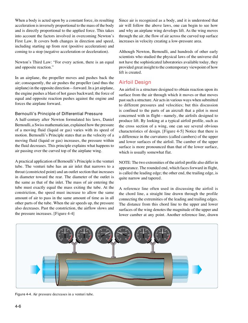
A practical application of Bernoulli’s Principle is the venturi
NOTE: The two extremities of the airfoil profile also differ in
tube. The venturi tube has an air inlet that narrows to a
appearance. The rounded end, which faces forward in flight,
throat (constricted point) and an outlet section that increases
is called the leading edge; the other end, the trailing edge, is
in diameter toward the rear. The diameter of the outlet is
quite narrow and tapered.
the same as that of the inlet. The mass of air entering the
tube must exactly equal the mass exiting the tube. At the
A reference line often used in discussing the airfoil is
constriction, the speed must increase to allow the same
the chord line, a straight line drawn through the profile
amount of air to pass in the same amount of time as in all
connecting the extremities of the leading and trailing edges.
other parts of the tube. When the air speeds up, the pressure
The distance from this chord line to the upper and lower
also decreases. Past the constriction, the airflow slows and
surfaces of the wing denotes the magnitude of the upper and
the pressure increases. [Figure 4-4]
lower camber at any point. Another reference line, drawn
4 6 4 6 4 6 4 6 4 6 4 6
VELOCITY PRESSURE VELOCITY PRESSURE VELOCITY PRESSURE
2 8 2 8 2 8 2 8 2 8 2 8
0 I0 0 I0 0 I0 0 I0 0 I0 0 I0
Figure 4-4. Air pressure decreases in a venturi tube.
4-6