FAA-H-8083-25C · Source PDF page 128
Aerodynamics of Flight
Coefficient of Lift Curve · PHAK page 5-31
Searchable transcription
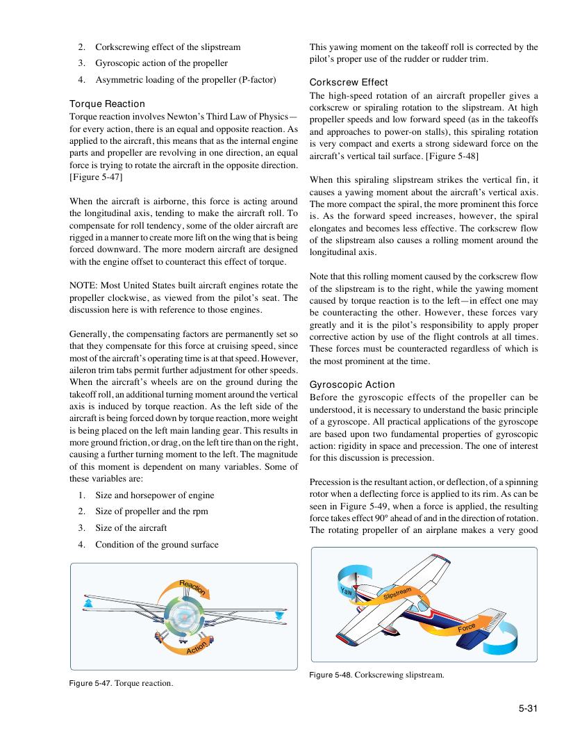
Reaction
Action
Figure 5-47. Torque reaction.
5-31
Y a w
2. Corkscrewing effect of the slipstream This yawing moment on the takeoff roll is corrected by the
pilot’s proper use of the rudder or rudder trim.
3. Gyroscopic action of the propeller
4. Asymmetric loading of the propeller (P-factor)
Corkscrew Effect
The high-speed rotation of an aircraft propeller gives a
Torque Reaction corkscrew or spiraling rotation to the slipstream. At high
Torque reaction involves Newton’s Third Law of Physics—
propeller speeds and low forward speed (as in the takeoffs
for every action, there is an equal and opposite reaction. As
and approaches to power-on stalls), this spiraling rotation
applied to the aircraft, this means that as the internal engine
is very compact and exerts a strong sideward force on the
parts and propeller are revolving in one direction, an equal
aircraft’s vertical tail surface. [Figure 5-48]
force is trying to rotate the aircraft in the opposite direction.
[Figure 5-47]
When this spiraling slipstream strikes the vertical fin, it
causes a yawing moment about the aircraft’s vertical axis.
When the aircraft is airborne, this force is acting around
The more compact the spiral, the more prominent this force
the longitudinal axis, tending to make the aircraft roll. To
is. As the forward speed increases, however, the spiral
compensate for roll tendency, some of the older aircraft are
elongates and becomes less effective. The corkscrew flow
rigged in a manner to create more lift on the wing that is being
of the slipstream also causes a rolling moment around the
forced downward. The more modern aircraft are designed
longitudinal axis.
with the engine offset to counteract this effect of torque.
Note that this rolling moment caused by the corkscrew flow
NOTE: Most United States built aircraft engines rotate the
of the slipstream is to the right, while the yawing moment
propeller clockwise, as viewed from the pilot’s seat. The
caused by torque reaction is to the left—in effect one may
discussion here is with reference to those engines.
be counteracting the other. However, these forces vary
greatly and it is the pilot’s responsibility to apply proper
Generally, the compensating factors are permanently set so
corrective action by use of the flight controls at all times.
that they compensate for this force at cruising speed, since
These forces must be counteracted regardless of which is
most of the aircraft’s operating time is at that speed. However,
the most prominent at the time.
aileron trim tabs permit further adjustment for other speeds.
When the aircraft’s wheels are on the ground during the
Gyroscopic Action
takeoff roll, an additional turning moment around the vertical
Before the gyroscopic effects of the propeller can be
axis is induced by torque reaction. As the left side of the
understood, it is necessary to understand the basic principle
aircraft is being forced down by torque reaction, more weight
of a gyroscope. All practical applications of the gyroscope
is being placed on the left main landing gear. This results in
are based upon two fundamental properties of gyroscopic
more ground friction, or drag, on the left tire than on the right,
action: rigidity in space and precession. The one of interest
causing a further turning moment to the left. The magnitude
for this discussion is precession.
of this moment is dependent on many variables. Some of
these variables are:
Precession is the resultant action, or deflection, of a spinning
1. Size and horsepower of engine rotor when a deflecting force is applied to its rim. As can be
seen in Figure 5-49, when a force is applied, the resulting
2. Size of propeller and the rpm
force takes effect 90° ahead of and in the direction of rotation.
3. Size of the aircraft The rotating propeller of an airplane makes a very good
4. Condition of the ground surface
Slipstream
Force
Figure 5-48. Corkscrewing slipstream.