FAA-H-8083-25C · Source PDF page 147
Aerodynamics of Flight
Laminar Boundary Layer Flow · PHAK page 5-50
Searchable transcription
Rudder Inboard wing
Elevator
Tab Outboard wing
Stabilizer
Foreflap
Midflap
Inboard flap
Aftflap
Flight spoilers
Ground spoiler
Outboard flap Aileron
Tab
Landing Flaps
Aileron
Leading edge slats
Inboard wing
Leading edge flaps
737 Control Surfaces
Outboard wing
Control tab Stabilizer
Inboard aileron Elevator
Leading edge flaps Control tab
Aileron
Upper rudder
Takeoff Flaps
Anti-balance tabs
Lower rudder
Foreflap Midflap Aftflap
Vortex generators
Pitot tubes
Inboard wing
Ground spoilers
Inboard flaps
Outboard wing
Flight spoilers
Outboard flap
Leading edge slat
Balance tab
Leading edge flap
Outboard aileron
Slats
Fence Aileron
727 Control Surfaces Flaps Retracted
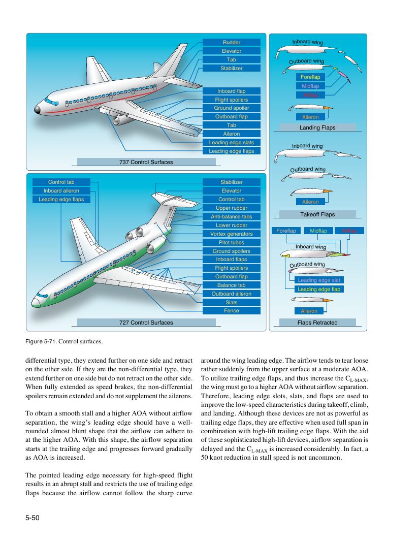
Figure 5-71. Control surfaces.
differential type, they extend further on one side and retract around the wing leading edge. The airflow tends to tear loose
on the other side. If they are the non-differential type, they rather suddenly from the upper surface at a moderate AOA.
extend further on one side but do not retract on the other side. To utilize trailing edge flaps, and thus increase the C ,
L-MAX
When fully extended as speed brakes, the non-differential the wing must go to a higher AOA without airflow separation.
spoilers remain extended and do not supplement the ailerons. Therefore, leading edge slots, slats, and flaps are used to
improve the low-speed characteristics during takeoff, climb,
To obtain a smooth stall and a higher AOA without airflow and landing. Although these devices are not as powerful as
separation, the wing’s leading edge should have a well- trailing edge flaps, they are effective when used full span in
rounded almost blunt shape that the airflow can adhere to combination with high-lift trailing edge flaps. With the aid
at the higher AOA. With this shape, the airflow separation of these sophisticated high-lift devices, airflow separation is
starts at the trailing edge and progresses forward gradually delayed and the C is increased considerably. In fact, a
L-MAX
as AOA is increased. 50 knot reduction in stall speed is not uncommon.
The pointed leading edge necessary for high-speed flight
results in an abrupt stall and restricts the use of trailing edge
flaps because the airflow cannot follow the sharp curve
5-50