FAA-H-8083-25C · Source PDF page 150
Flight Controls
Flight Control Systems · PHAK page 6-2
Searchable transcription
YYaaww
Cyclic stick
cilcyC Cyclic
YYaaww
Cyclic Cyclic
CCoolllleeccttiivvee
Anti-torque pedals Collective lever
6-2
CC oo eellll cc vviitt ee
of this project is to develop an adaptive neural network-based
Control stick flight control system. Applied directly to flight control system
feedback errors, IFCS provides adjustments to improve
Elevator
aircraft performance in normal flight, as well as with system
failures. With IFCS, a pilot is able to maintain control and
Pulleys
safely land an aircraft that has suffered a failure to a control
surface or damage to the airframe. It also improves mission
capability, increases the reliability and safety of flight, and
eases the pilot workload.
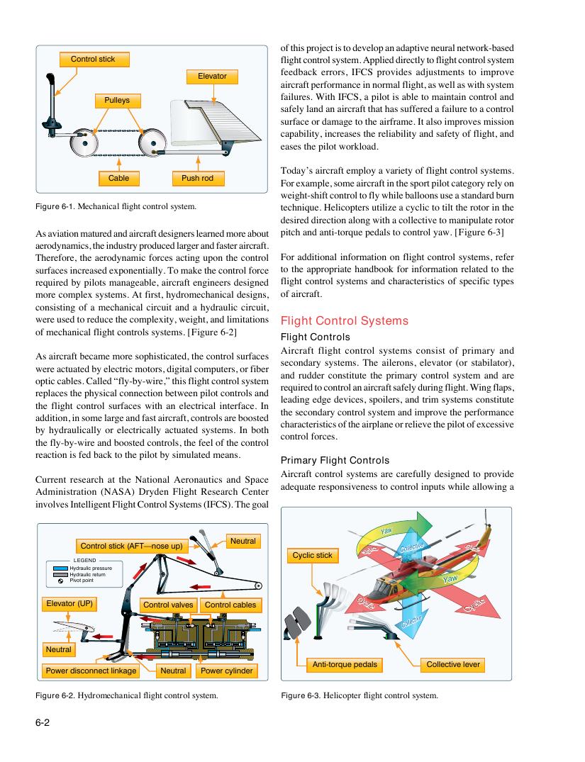
Today’s aircraft employ a variety of flight control systems.
Cable Push rod
For example, some aircraft in the sport pilot category rely on
weight-shift control to fly while balloons use a standard burn
Figure 6-1. Mechanical flight control system. technique. Helicopters utilize a cyclic to tilt the rotor in the
desired direction along with a collective to manipulate rotor
As aviation matured and aircraft designers learned more about pitch and anti-torque pedals to control yaw. [Figure 6-3]
aerodynamics, the industry produced larger and faster aircraft.
Therefore, the aerodynamic forces acting upon the control For additional information on flight control systems, refer
surfaces increased exponentially. To make the control force to the appropriate handbook for information related to the
required by pilots manageable, aircraft engineers designed flight control systems and characteristics of specific types
more complex systems. At first, hydromechanical designs, of aircraft.
consisting of a mechanical circuit and a hydraulic circuit,
were used to reduce the complexity, weight, and limitations Flight Control Systems
of mechanical flight controls systems. [Figure 6-2]
Flight Controls
Aircraft flight control systems consist of primary and
As aircraft became more sophisticated, the control surfaces
secondary systems. The ailerons, elevator (or stabilator),
were actuated by electric motors, digital computers, or fiber
and rudder constitute the primary control system and are
optic cables. Called “fly-by-wire,” this flight control system
required to control an aircraft safely during flight. Wing flaps,
replaces the physical connection between pilot controls and
leading edge devices, spoilers, and trim systems constitute
the flight control surfaces with an electrical interface. In
the secondary control system and improve the performance
addition, in some large and fast aircraft, controls are boosted
characteristics of the airplane or relieve the pilot of excessive
by hydraulically or electrically actuated systems. In both
control forces.
the fly-by-wire and boosted controls, the feel of the control
reaction is fed back to the pilot by simulated means.
Primary Flight Controls
Aircraft control systems are carefully designed to provide
Current research at the National Aeronautics and Space
adequate responsiveness to control inputs while allowing a
Administration (NASA) Dryden Flight Research Center
involves Intelligent Flight Control Systems (IFCS). The goal
Neutral
Control stick (AFT—nose up)
LEGEND
Hydraulic pressure
Hydraulic return
Pivot point
Elevator (UP) Control valves Control cables
Neutral
Power disconnect linkage Neutral Power cylinder
Figure 6-2. Hydromechanical flight control system. Figure 6-3. Helicopter flight control system.