FAA-H-8083-25C · Source PDF page 151
Flight Controls
Ailerons · PHAK page 6-3
Searchable transcription
s ( L l t o a a n t b e g i r l i i a t t u y l d ) a i x n i a s l
6-3
A eli r o n — R o ll
E levator— Rudder—Yaw
P itch Las oxa
t
nsib u ti g al (
y tili
de t) ni a r l a l Vertical axis (directional stability)
L
ift
Drag
Primary
Airplane Axes of Type of
Control Movement Rotation Stability Surface
Aileron Roll Longitudinal Lateral
Elevator/
Pitch Lateral Longitudinal
Stabilator
Rudder Yaw Vertical Directional
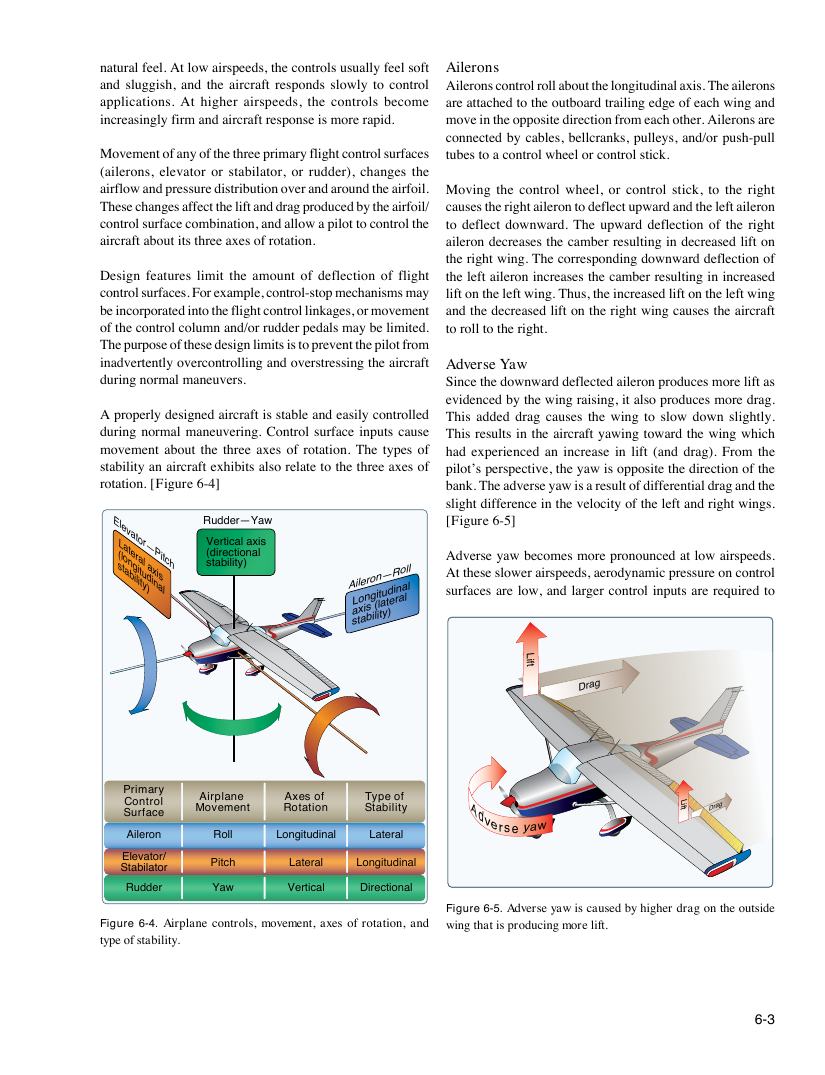
Figure 6-5. Adverse yaw is caused by higher drag on the outside
Figure 6-4. Airplane controls, movement, axes of rotation, and wing that is producing more lift.
type of stability.
Lift D ar g A d
v e rse y a w
natural feel. At low airspeeds, the controls usually feel soft Ailerons
and sluggish, and the aircraft responds slowly to control Ailerons control roll about the longitudinal axis. The ailerons
applications. At higher airspeeds, the controls become are attached to the outboard trailing edge of each wing and
increasingly firm and aircraft response is more rapid. move in the opposite direction from each other. Ailerons are
connected by cables, bellcranks, pulleys, and/or push-pull
Movement of any of the three primary flight control surfaces tubes to a control wheel or control stick.
(ailerons, elevator or stabilator, or rudder), changes the
airflow and pressure distribution over and around the airfoil. Moving the control wheel, or control stick, to the right
These changes affect the lift and drag produced by the airfoil/ causes the right aileron to deflect upward and the left aileron
control surface combination, and allow a pilot to control the to deflect downward. The upward deflection of the right
aircraft about its three axes of rotation. aileron decreases the camber resulting in decreased lift on
the right wing. The corresponding downward deflection of
Design features limit the amount of deflection of flight the left aileron increases the camber resulting in increased
control surfaces. For example, control-stop mechanisms may lift on the left wing. Thus, the increased lift on the left wing
be incorporated into the flight control linkages, or movement and the decreased lift on the right wing causes the aircraft
of the control column and/or rudder pedals may be limited. to roll to the right.
The purpose of these design limits is to prevent the pilot from
inadvertently overcontrolling and overstressing the aircraft Adverse Yaw
during normal maneuvers. Since the downward deflected aileron produces more lift as
evidenced by the wing raising, it also produces more drag.
A properly designed aircraft is stable and easily controlled This added drag causes the wing to slow down slightly.
during normal maneuvering. Control surface inputs cause This results in the aircraft yawing toward the wing which
movement about the three axes of rotation. The types of had experienced an increase in lift (and drag). From the
stability an aircraft exhibits also relate to the three axes of pilot’s perspective, the yaw is opposite the direction of the
rotation. [Figure 6-4] bank. The adverse yaw is a result of differential drag and the
slight difference in the velocity of the left and right wings.
[Figure 6-5]
Adverse yaw becomes more pronounced at low airspeeds. At these slower airspeeds, aerodynamic pressure on control surfaces are low, and larger control inputs are required to