FAA-H-8083-25C · Source PDF page 157
Flight Controls
Leading Edge Devices · PHAK page 6-9
Searchable transcription
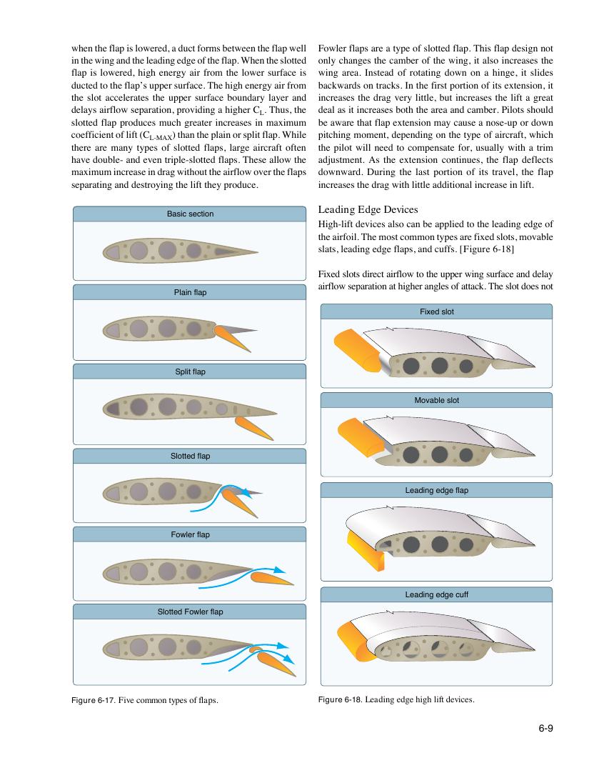
when the flap is lowered, a duct forms between the flap well Fowler flaps are a type of slotted flap. This flap design not
in the wing and the leading edge of the flap. When the slotted only changes the camber of the wing, it also increases the
flap is lowered, high energy air from the lower surface is wing area. Instead of rotating down on a hinge, it slides
ducted to the flap’s upper surface. The high energy air from backwards on tracks. In the first portion of its extension, it
the slot accelerates the upper surface boundary layer and increases the drag very little, but increases the lift a great
delays airflow separation, providing a higher C . Thus, the deal as it increases both the area and camber. Pilots should
L
slotted flap produces much greater increases in maximum be aware that flap extension may cause a nose-up or down
coefficient of lift (C ) than the plain or split flap. While pitching moment, depending on the type of aircraft, which
L-MAX
there are many types of slotted flaps, large aircraft often the pilot will need to compensate for, usually with a trim
have double- and even triple-slotted flaps. These allow the adjustment. As the extension continues, the flap deflects
maximum increase in drag without the airflow over the flaps downward. During the last portion of its travel, the flap
separating and destroying the lift they produce. increases the drag with little additional increase in lift.
Leading Edge Devices
Basic section
High-lift devices also can be applied to the leading edge of
the airfoil. The most common types are fixed slots, movable
slats, leading edge flaps, and cuffs. [Figure 6-18]
Fixed slots direct airflow to the upper wing surface and delay
airflow separation at higher angles of attack. The slot does not
Plain flap
Fixed slot
Split flap
Movable slot
Slotted flap
Leading edge flap
Fowler flap
Leading edge cuff
Slotted Fowler flap
Figure 6-17. Five common types of flaps. Figure 6-18. Leading edge high lift devices.
6-9