FAA-H-8083-25C · Source PDF page 162
Aircraft Systems
Aircraft Systems · PHAK page 7-2
Searchable transcription
Reciprocating Engines
Most small aircraft are designed with reciprocating
engines. The name is derived from the back-and-forth, or
reciprocating, movement of the pistons that produces the
mechanical energy necessary to accomplish work.
Driven by a revitalization of the general aviation (GA)
industry and advances in both material and engine design,
reciprocating engine technology has improved dramatically
over the past two decades. The integration of computerized
engine management systems has improved fuel efficiency,
decreased emissions, and reduced pilot workload.
Reciprocating engines operate on the basic principle of
converting chemical energy (fuel) into mechanical energy.
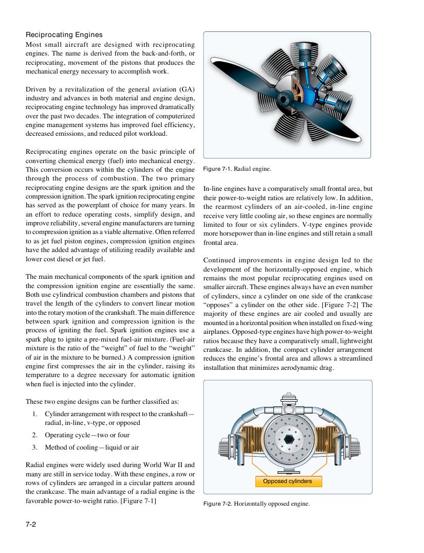
This conversion occurs within the cylinders of the engine Figure 7-1. Radial engine.
through the process of combustion. The two primary
reciprocating engine designs are the spark ignition and the In-line engines have a comparatively small frontal area, but
compression ignition. The spark ignition reciprocating engine their power-to-weight ratios are relatively low. In addition,
has served as the powerplant of choice for many years. In the rearmost cylinders of an air-cooled, in-line engine
an effort to reduce operating costs, simplify design, and receive very little cooling air, so these engines are normally
improve reliability, several engine manufacturers are turning limited to four or six cylinders. V-type engines provide
to compression ignition as a viable alternative. Often referred more horsepower than in-line engines and still retain a small
to as jet fuel piston engines, compression ignition engines frontal area.
have the added advantage of utilizing readily available and
lower cost diesel or jet fuel. Continued improvements in engine design led to the
development of the horizontally-opposed engine, which
The main mechanical components of the spark ignition and remains the most popular reciprocating engines used on
the compression ignition engine are essentially the same. smaller aircraft. These engines always have an even number
Both use cylindrical combustion chambers and pistons that of cylinders, since a cylinder on one side of the crankcase
travel the length of the cylinders to convert linear motion “opposes” a cylinder on the other side. [Figure 7-2] The
into the rotary motion of the crankshaft. The main difference majority of these engines are air cooled and usually are
between spark ignition and compression ignition is the mounted in a horizontal position when installed on fixed-wing
process of igniting the fuel. Spark ignition engines use a airplanes. Opposed-type engines have high power-to-weight
spark plug to ignite a pre-mixed fuel-air mixture. (Fuel-air ratios because they have a comparatively small, lightweight
mixture is the ratio of the “weight” of fuel to the “weight” crankcase. In addition, the compact cylinder arrangement
of air in the mixture to be burned.) A compression ignition reduces the engine’s frontal area and allows a streamlined
engine first compresses the air in the cylinder, raising its installation that minimizes aerodynamic drag.
temperature to a degree necessary for automatic ignition
when fuel is injected into the cylinder.
These two engine designs can be further classified as:
1. Cylinder arrangement with respect to the crankshaft—
radial, in-line, v-type, or opposed
2. Operating cycle—two or four
3. Method of cooling—liquid or air
Radial engines were widely used during World War II and
many are still in service today. With these engines, a row or
rows of cylinders are arranged in a circular pattern around Opposed cylinders
the crankcase. The main advantage of a radial engine is the
favorable power-to-weight ratio. [Figure 7-1]
Figure 7-2. Horizontally opposed engine.
7-2