FAA-H-8083-25C · Source PDF page 163
Aircraft Systems
Aircraft Systems · PHAK page 7-3
Searchable transcription
Depending on the engine manufacturer, all of these
arrangements can be designed to utilize spark or compression
Cylinder
ignition and operate on either a two- or four-stroke cycle.
In a two-stroke engine, the conversion of chemical energy
into mechanical energy occurs over a two-stroke operating
cycle. The intake, compression, power, and exhaust processes
occur in only two strokes of the piston rather than the more
common four strokes. Because a two-stroke engine has
a power stroke upon each revolution of the crankshaft, it
typically has higher power-to-weight ratio than a comparable
four-stroke engine. Due to the inherent inefficiency and Exhaust valve
Intake valve
disproportionate emissions of the earliest designs, use of the
two-stroke engine has been limited in aviation.
Recent advances in material and engine design have
reduced many of the negative characteristics associated
with two-stroke engines. Modern two-stroke engines often
Spark plug
use conventional oil sumps, oil pumps, and full pressure
Piston
fed lubrication systems. The use of direct fuel injection
Crankcase
and pressurized air, characteristic of advanced compression
ignition engines, make two-stroke compression ignition
engines a viable alternative to the more common four-stroke
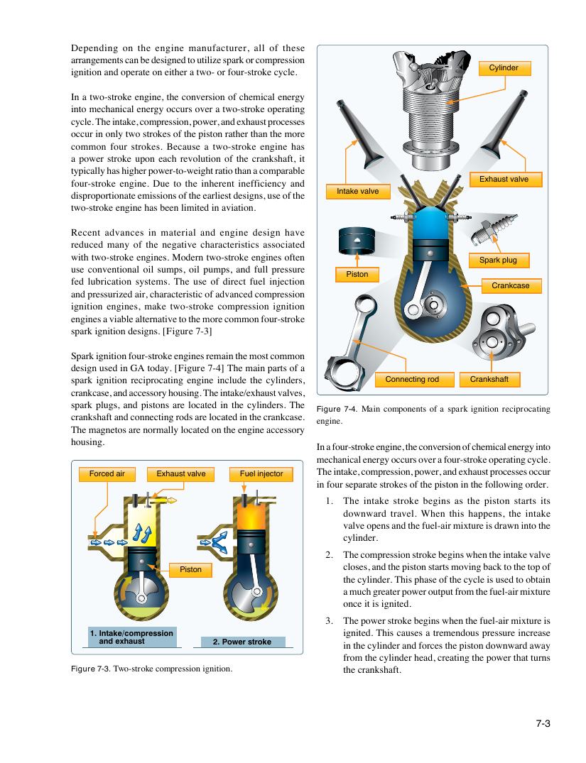
spark ignition designs. [Figure 7-3]
Spark ignition four-stroke engines remain the most common
design used in GA today. [Figure 7-4] The main parts of a
spark ignition reciprocating engine include the cylinders, Connecting rod Crankshaft
crankcase, and accessory housing. The intake/exhaust valves,
spark plugs, and pistons are located in the cylinders. The
Figure 7-4. Main components of a spark ignition reciprocating
crankshaft and connecting rods are located in the crankcase.
engine.
The magnetos are normally located on the engine accessory
housing.
In a four-stroke engine, the conversion of chemical energy into
mechanical energy occurs over a four-stroke operating cycle.
The intake, compression, power, and exhaust processes occur
Forced air Exhaust valve Fuel injector
in four separate strokes of the piston in the following order.
1. The intake stroke begins as the piston starts its
downward travel. When this happens, the intake
valve opens and the fuel-air mixture is drawn into the
cylinder.
2. The compression stroke begins when the intake valve
closes, and the piston starts moving back to the top of
Piston
the cylinder. This phase of the cycle is used to obtain
a much greater power output from the fuel-air mixture
once it is ignited.
3. The power stroke begins when the fuel-air mixture is
1. Intake/compression ignited. This causes a tremendous pressure increase
and exhaust 2. Power stroke in the cylinder and forces the piston downward away
from the cylinder head, creating the power that turns
Figure 7-3. Two-stroke compression ignition. the crankshaft.
7-3