FAA-H-8083-25C · Source PDF page 185
Aircraft Systems
Airframe Systems · PHAK page 7-25
Searchable transcription
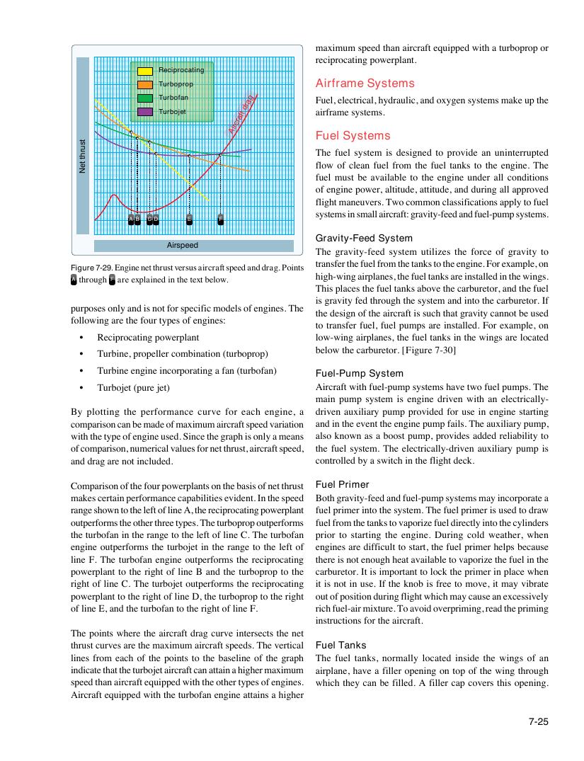
Figure 7-29. Engine net thrust versus aircraft speed and drag. Points
A through F are explained in the text below.
7-25
tsurht
teN
maximum speed than aircraft equipped with a turboprop or
reciprocating powerplant.
Reciprocating
Turboprop Airframe Systems
Turbofan a g Fuel, electrical, hydraulic, and oxygen systems make up the
dr
Turbojet aft airframe systems.
cr
Air
F
Th
u
e
e
f
l
u
S
el
y
s
s
ys
t
t
e
e
m
m
s
is designed to provide an uninterrupted
flow of clean fuel from the fuel tanks to the engine. The
fuel must be available to the engine under all conditions
of engine power, altitude, attitude, and during all approved
flight maneuvers. Two common classifications apply to fuel
systems in small aircraft: gravity-feed and fuel-pump systems.
A B C D E F
Gravity-Feed System
Airspeed
The gravity-feed system utilizes the force of gravity to
transfer the fuel from the tanks to the engine. For example, on
high-wing airplanes, the fuel tanks are installed in the wings.
This places the fuel tanks above the carburetor, and the fuel
is gravity fed through the system and into the carburetor. If
purposes only and is not for specific models of engines. The
the design of the aircraft is such that gravity cannot be used
following are the four types of engines:
to transfer fuel, fuel pumps are installed. For example, on
• Reciprocating powerplant low-wing airplanes, the fuel tanks in the wings are located
below the carburetor. [Figure 7-30]
• Turbine, propeller combination (turboprop)
• Turbine engine incorporating a fan (turbofan)
Fuel-Pump System
• Turbojet (pure jet) Aircraft with fuel-pump systems have two fuel pumps. The
main pump system is engine driven with an electrically-
By plotting the performance curve for each engine, a driven auxiliary pump provided for use in engine starting
comparison can be made of maximum aircraft speed variation and in the event the engine pump fails. The auxiliary pump,
with the type of engine used. Since the graph is only a means also known as a boost pump, provides added reliability to
of comparison, numerical values for net thrust, aircraft speed, the fuel system. The electrically-driven auxiliary pump is
and drag are not included. controlled by a switch in the flight deck.
Comparison of the four powerplants on the basis of net thrust Fuel Primer
makes certain performance capabilities evident. In the speed Both gravity-feed and fuel-pump systems may incorporate a
range shown to the left of line A, the reciprocating powerplant fuel primer into the system. The fuel primer is used to draw
outperforms the other three types. The turboprop outperforms fuel from the tanks to vaporize fuel directly into the cylinders
the turbofan in the range to the left of line C. The turbofan prior to starting the engine. During cold weather, when
engine outperforms the turbojet in the range to the left of engines are difficult to start, the fuel primer helps because
line F. The turbofan engine outperforms the reciprocating there is not enough heat available to vaporize the fuel in the
powerplant to the right of line B and the turboprop to the carburetor. It is important to lock the primer in place when
right of line C. The turbojet outperforms the reciprocating it is not in use. If the knob is free to move, it may vibrate
powerplant to the right of line D, the turboprop to the right out of position during flight which may cause an excessively
of line E, and the turbofan to the right of line F. rich fuel-air mixture. To avoid overpriming, read the priming
instructions for the aircraft.
The points where the aircraft drag curve intersects the net
thrust curves are the maximum aircraft speeds. The vertical Fuel Tanks
lines from each of the points to the baseline of the graph The fuel tanks, normally located inside the wings of an
indicate that the turbojet aircraft can attain a higher maximum airplane, have a filler opening on top of the wing through
speed than aircraft equipped with the other types of engines. which they can be filled. A filler cap covers this opening.
Aircraft equipped with the turbofan engine attains a higher