FAA-H-8083-25C · Source PDF page 192
Aircraft Systems
Hydraulic Systems · PHAK page 7-32
Searchable transcription
Low-voltage
Alternator
warning light
control unit
To inst
Low volt out LTS To fuel quantity indicators
circuit P
Power in breaker R FUEL IND.
Sense (+) I To flashing beacon
F Alternator
Field M To pitot heat
BCN PITOT
A
Sense (-) To radio cooling fan
G B R
Ground B Pull off Y P O U F L F L R S A T D R IO O B F E A N To strobe lights
To landing and taxi lights
B
ALT U LDG LTS
To ignition switch
S
Alternator field To wing flap system
circuit breaker FLAP
Clock
To red doorpost maplight
Ammeter To low-voltage warning light
Master INST LTS To instrument, radio, compass
switch
and post lights
Starter
To oil temperature gauge
Oil pressure
switch To turn coordinator
To low-vacuum warning light
A
V Switch/circuit breaker to
standby vacuum pump
I
STBY VAC
O To white doorpost light
To wing N To audio muting relay
flap circuit
Flight hour Starter breaker I To control wheel maplight
recorder contactor C
S D N O A M V E To navigation lights
To dome light
B
To radio
U
S RADIO 1 Magnetos To radio
RADIO 2
To radio or transponder
and encoding altimeter
Circuit breaker (auto-reset) Fuse Diode RADIO 3
Resistor
To radio
Circuit breaker (push to reset) RADIO 4
Circuit breaker (pull—off,
Capacitor (Noise Filter)
push to reset)
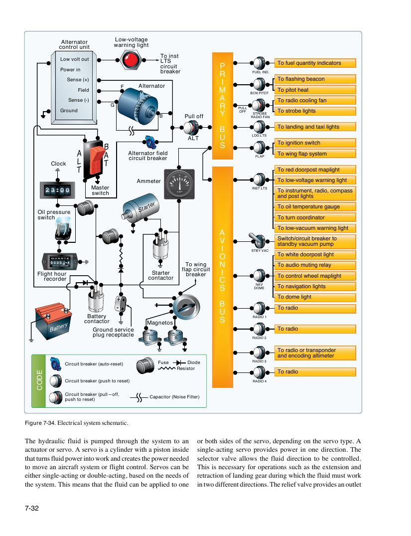
Figure 7-34. Electrical system schematic.
7-32
B a t t e r y
ALT
BAT
-30 0 +30
- 60 + 60
A M P
Battery contactor Ground service
plug receptacle
L R
EDOC
The hydraulic fluid is pumped through the system to an or both sides of the servo, depending on the servo type. A
actuator or servo. A servo is a cylinder with a piston inside single-acting servo provides power in one direction. The
that turns fluid power into work and creates the power needed selector valve allows the fluid direction to be controlled.
to move an aircraft system or flight control. Servos can be This is necessary for operations such as the extension and
either single-acting or double-acting, based on the needs of retraction of landing gear during which the fluid must work
the system. This means that the fluid can be applied to one in two different directions. The relief valve provides an outlet