FAA-H-8083-25C · Source PDF page 196
Aircraft Systems
Pressurized Aircraft · PHAK page 7-36
Searchable transcription
in a corresponding increase in cabin altitude. Differential Decompression is defined as the inability of the aircraft’s
control is used to prevent the maximum differential pressure, pressurization system to maintain its designed pressure
for which the fuselage was designed, from being exceeded. differential. This can be caused by a malfunction in the
This differential pressure is determined by the structural pressurization system or structural damage to the aircraft.
strength of the cabin and often by the relationship of the
cabin size to the probable areas of rupture, such as window Physiologically, decompressions fall into the following two
areas and doors. categories:
• Explosive decompression—a change in cabin pressure
The cabin air pressure safety valve is a combination
faster than the lungs can decompress, possibly
pressure relief, vacuum relief, and dump valve. The pressure
resulting in lung damage. Normally, the time required
relief valve prevents cabin pressure from exceeding a
to release air from the lungs without restrictions, such
predetermined differential pressure above ambient pressure.
as masks, is 0.2 seconds. Most authorities consider any
The vacuum relief prevents ambient pressure from exceeding
decompression that occurs in less than 0.5 seconds to
cabin pressure by allowing external air to enter the cabin
be explosive and potentially dangerous.
when ambient pressure exceeds cabin pressure. The flight
• Rapid decompression—a change in cabin pressure in
deck control switch actuates the dump valve. When this
which the lungs decompress faster than the cabin.
switch is positioned to ram, a solenoid valve opens, causing
the valve to dump cabin air into the atmosphere.
During an explosive decompression, there may be noise,
and one may feel dazed for a moment. The cabin air fills
The degree of pressurization and the operating altitude of
with fog, dust, or flying debris. Fog occurs due to the rapid
the aircraft are limited by several critical design factors.
drop in temperature and the change of relative humidity.
Primarily, the fuselage is designed to withstand a particular
Normally, the ears clear automatically. Air rushes from the
maximum cabin differential pressure.
mouth and nose due to the escape of air from the lungs and
may be noticed by some individuals.
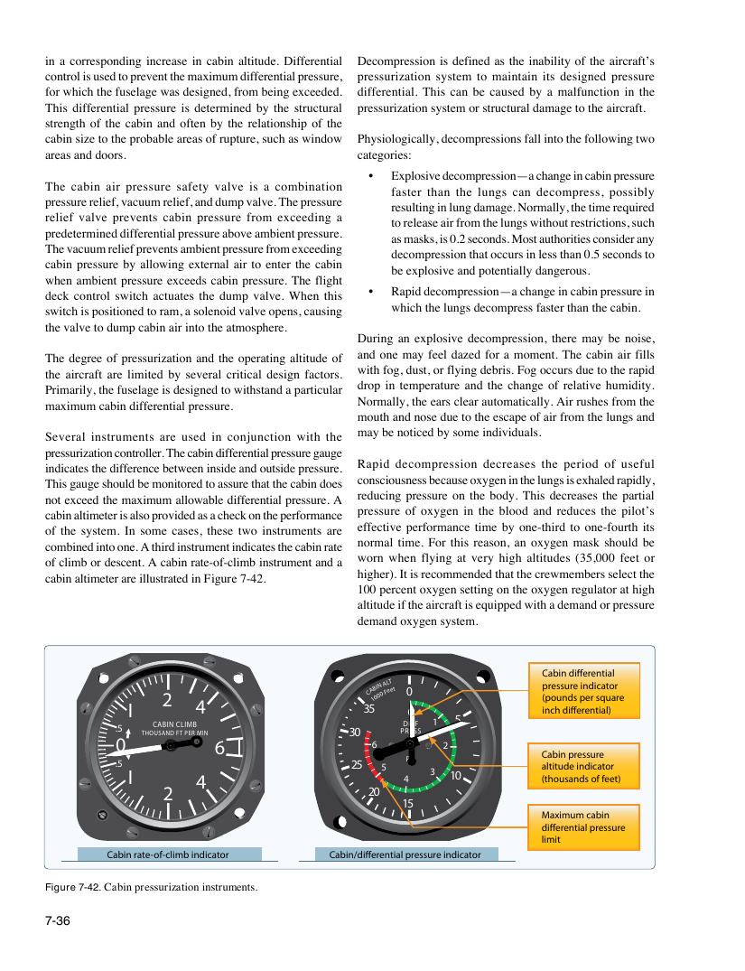
Several instruments are used in conjunction with the
pressurization controller. The cabin differential pressure gauge
Rapid decompression decreases the period of useful
indicates the difference between inside and outside pressure.
consciousness because oxygen in the lungs is exhaled rapidly,
This gauge should be monitored to assure that the cabin does
reducing pressure on the body. This decreases the partial
not exceed the maximum allowable differential pressure. A
pressure of oxygen in the blood and reduces the pilot’s
cabin altimeter is also provided as a check on the performance
effective performance time by one-third to one-fourth its
of the system. In some cases, these two instruments are
normal time. For this reason, an oxygen mask should be
combined into one. A third instrument indicates the cabin rate
worn when flying at very high altitudes (35,000 feet or
of climb or descent. A cabin rate-of-climb instrument and a
higher). It is recommended that the crewmembers select the
cabin altimeter are illustrated in Figure 7-42.
100 percent oxygen setting on the oxygen regulator at high
altitude if the aircraft is equipped with a demand or pressure
demand oxygen system.
Cabin differential
2 4 CA 1 B 0 I 0 N 0 A F L e T et 0 p (p r o es u s n u d re s p in e d r i s c q a u to a r re
I 35 0 inch differential)
.5 THO C U A SA B N IN D C FT L I P M ER B MIN 30 P D R I E F S F S 1 5
0 6 6 2
Cabin pressure
PSI
.5 25 5 altitude indicator
I 3 10
4 4 (thousands of feet)
2 20
15
Maximum cabin
differential pressure
limit
Cabin rate-of-climb indicator Cabin/differential pressure indicator
Figure 7-42. Cabin pressurization instruments.
7-36