FAA-H-8083-25C · Source PDF page 181
Aircraft Systems
Turbofan · PHAK page 7-21
Searchable transcription
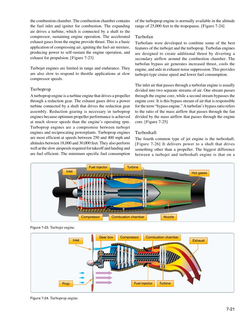
the combustion chamber. The combustion chamber contains of the turboprop engine is normally available in the altitude
the fuel inlet and igniter for combustion. The expanding range of 25,000 feet to the tropopause. [Figure 7-24]
air drives a turbine, which is connected by a shaft to the
compressor, sustaining engine operation. The accelerated Turbofan
exhaust gases from the engine provide thrust. This is a basic Turbofans were developed to combine some of the best
application of compressing air, igniting the fuel-air mixture, features of the turbojet and the turboprop. Turbofan engines
producing power to self-sustain the engine operation, and are designed to create additional thrust by diverting a
exhaust for propulsion. [Figure 7-23] secondary airflow around the combustion chamber. The
turbofan bypass air generates increased thrust, cools the
Turbojet engines are limited in range and endurance. They engine, and aids in exhaust noise suppression. This provides
are also slow to respond to throttle applications at slow turbojet-type cruise speed and lower fuel consumption.
compressor speeds.
The inlet air that passes through a turbofan engine is usually
Turboprop divided into two separate streams of air. One stream passes
A turboprop engine is a turbine engine that drives a propeller through the engine core, while a second stream bypasses the
through a reduction gear. The exhaust gases drive a power engine core. It is this bypass stream of air that is responsible
turbine connected by a shaft that drives the reduction gear for the term “bypass engine.” A turbofan’s bypass ratio refers
assembly. Reduction gearing is necessary in turboprop to the ratio of the mass airflow that passes through the fan
engines because optimum propeller performance is achieved divided by the mass airflow that passes through the engine
at much slower speeds than the engine’s operating rpm. core. [Figure 7-25]
Turboprop engines are a compromise between turbojet
engines and reciprocating powerplants. Turboprop engines Turboshaft
are most efficient at speeds between 250 and 400 mph and The fourth common type of jet engine is the turboshaft.
altitudes between 18,000 and 30,000 feet. They also perform [Figure 7-26] It delivers power to a shaft that drives
well at the slow airspeeds required for takeoff and landing and something other than a propeller. The biggest difference
are fuel efficient. The minimum specific fuel consumption between a turbojet and turboshaft engine is that on a
Fuel injector Turbine
Inlet
Hot gases
Compressor Combustion chamber Nozzle
Figure 7-23. Turbojet engine.
Gear box Compressor Combustion chamber
Inlet Exhaust
Prop Fuel injector Turbine
Figure 7-24. Turboprop engine.
7-21