FAA-H-8083-25C · Source PDF page 125
Aerodynamics of Flight
Coefficient of Lift Curve · PHAK page 5-28
Searchable transcription
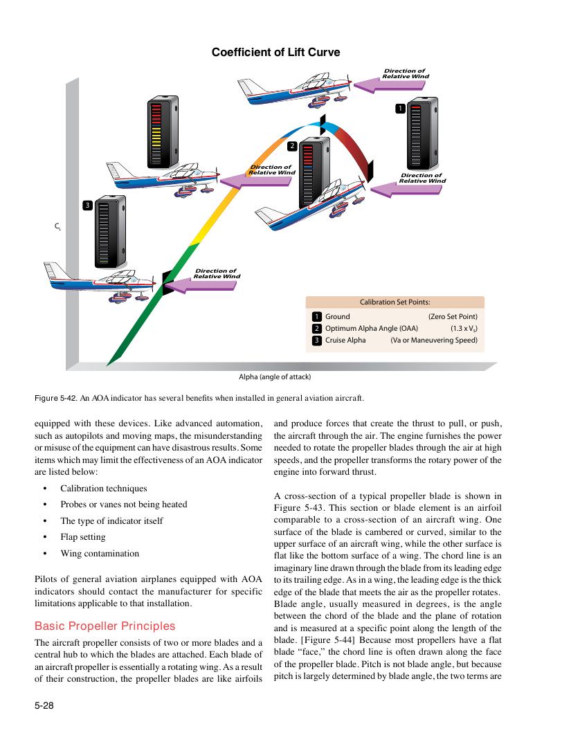
Coefficient of Lift Curve
Direction of
Relative Wind
1
2
Direction of
Relative Wind
Direction of
Relative Wind
3
C
L
Direction of
Relative Wind
Calibration Set Points:
1 Ground (Zero Set Point)
2 Optimum Alpha Angle (OAA) (1.3 x Vs)
3 Cruise Alpha (Va or Maneuvering Speed)
Alpha (angle of attack)
Figure 5-42. An AOA indicator has several benefits when installed in general aviation aircraft.
equipped with these devices. Like advanced automation, and produce forces that create the thrust to pull, or push,
such as autopilots and moving maps, the misunderstanding the aircraft through the air. The engine furnishes the power
or misuse of the equipment can have disastrous results. Some needed to rotate the propeller blades through the air at high
items which may limit the effectiveness of an AOA indicator speeds, and the propeller transforms the rotary power of the
are listed below: engine into forward thrust.
• Calibration techniques
A cross-section of a typical propeller blade is shown in
• Probes or vanes not being heated
Figure 5-43. This section or blade element is an airfoil
• The type of indicator itself comparable to a cross-section of an aircraft wing. One
surface of the blade is cambered or curved, similar to the
• Flap setting
upper surface of an aircraft wing, while the other surface is
• Wing contamination flat like the bottom surface of a wing. The chord line is an
imaginary line drawn through the blade from its leading edge
Pilots of general aviation airplanes equipped with AOA to its trailing edge. As in a wing, the leading edge is the thick
indicators should contact the manufacturer for specific edge of the blade that meets the air as the propeller rotates.
limitations applicable to that installation. Blade angle, usually measured in degrees, is the angle
between the chord of the blade and the plane of rotation
Basic Propeller Principles and is measured at a specific point along the length of the
The aircraft propeller consists of two or more blades and a blade. [Figure 5-44] Because most propellers have a flat
central hub to which the blades are attached. Each blade of blade “face,” the chord line is often drawn along the face
an aircraft propeller is essentially a rotating wing. As a result of the propeller blade. Pitch is not blade angle, but because
of their construction, the propeller blades are like airfoils pitch is largely determined by blade angle, the two terms are
5-28