FAA-H-8083-25C · Source PDF page 131
Aerodynamics of Flight
Load Factors · PHAK page 5-34
Searchable transcription
Centrifugal
force = 1.73 Gs
Load
factor
=
2 G
s
5-34
G1
=
ytivarG
7
6
60°
50°
40°
30°
20°
1
5
4
0 ° 3
2
1
0
0° 10° 20° 30° 40° 50° 60° 70° 80° 90°
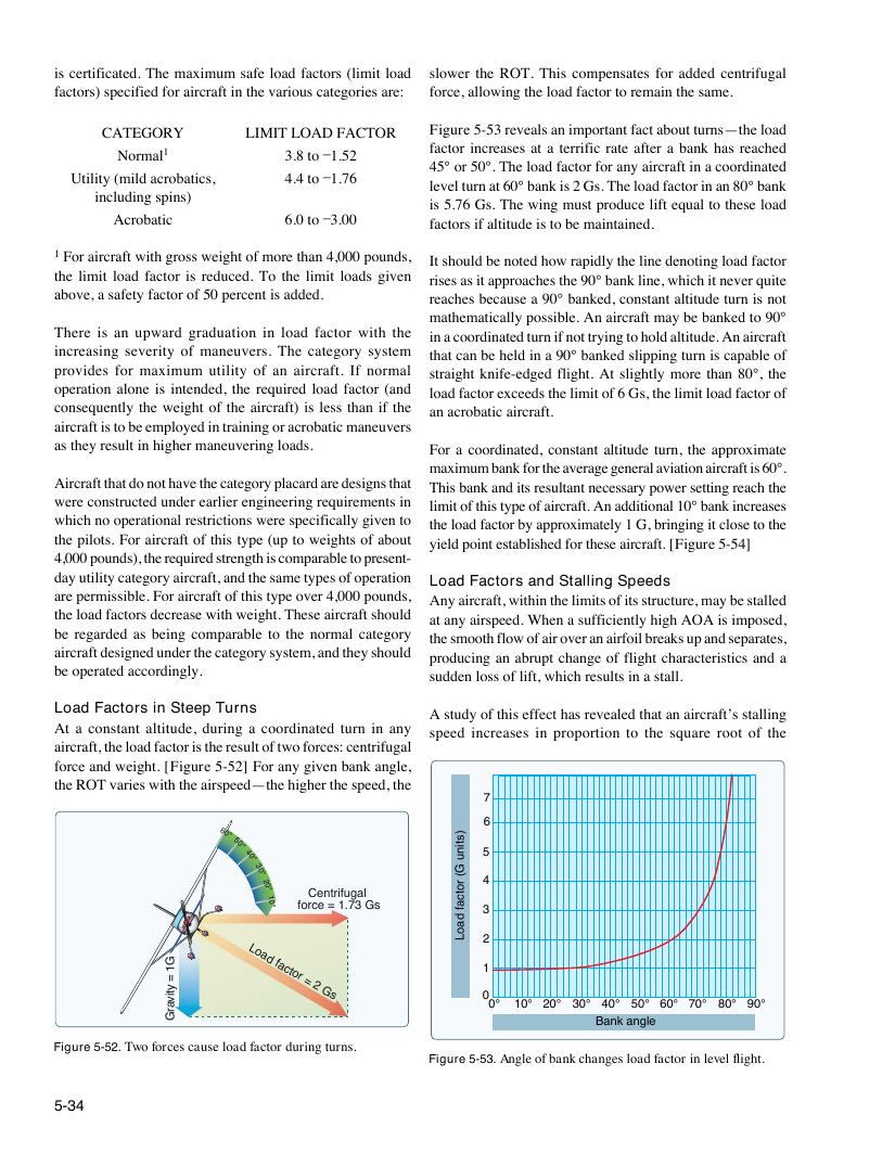
Figure 5-52. Two forces cause load factor during turns.
)stinu
G(
rotcaf
daoL
is certificated. The maximum safe load factors (limit load slower the ROT. This compensates for added centrifugal
factors) specified for aircraft in the various categories are: force, allowing the load factor to remain the same.
CATEGORY LIMIT LOAD FACTOR Figure 5-53 reveals an important fact about turns—the load
factor increases at a terrific rate after a bank has reached
Normal1 3.8 to –1.52
45° or 50°. The load factor for any aircraft in a coordinated
Utility (mild acrobatics, 4.4 to –1.76
level turn at 60° bank is 2 Gs. The load factor in an 80° bank
including spins)
is 5.76 Gs. The wing must produce lift equal to these load
Acrobatic 6.0 to –3.00 factors if altitude is to be maintained.
1 For aircraft with gross weight of more than 4,000 pounds, It should be noted how rapidly the line denoting load factor
the limit load factor is reduced. To the limit loads given rises as it approaches the 90° bank line, which it never quite
above, a safety factor of 50 percent is added. reaches because a 90° banked, constant altitude turn is not
mathematically possible. An aircraft may be banked to 90°
There is an upward graduation in load factor with the in a coordinated turn if not trying to hold altitude. An aircraft
increasing severity of maneuvers. The category system that can be held in a 90° banked slipping turn is capable of
provides for maximum utility of an aircraft. If normal straight knife-edged flight. At slightly more than 80°, the
operation alone is intended, the required load factor (and load factor exceeds the limit of 6 Gs, the limit load factor of
consequently the weight of the aircraft) is less than if the an acrobatic aircraft.
aircraft is to be employed in training or acrobatic maneuvers
as they result in higher maneuvering loads. For a coordinated, constant altitude turn, the approximate
maximum bank for the average general aviation aircraft is 60°.
Aircraft that do not have the category placard are designs that This bank and its resultant necessary power setting reach the
were constructed under earlier engineering requirements in limit of this type of aircraft. An additional 10° bank increases
which no operational restrictions were specifically given to the load factor by approximately 1 G, bringing it close to the
the pilots. For aircraft of this type (up to weights of about yield point established for these aircraft. [Figure 5-54]
4,000 pounds), the required strength is comparable to present-
day utility category aircraft, and the same types of operation
Load Factors and Stalling Speeds
are permissible. For aircraft of this type over 4,000 pounds,
Any aircraft, within the limits of its structure, may be stalled
the load factors decrease with weight. These aircraft should
at any airspeed. When a sufficiently high AOA is imposed,
be regarded as being comparable to the normal category
the smooth flow of air over an airfoil breaks up and separates,
aircraft designed under the category system, and they should
producing an abrupt change of flight characteristics and a
be operated accordingly.
sudden loss of lift, which results in a stall.
Load Factors in Steep Turns A study of this effect has revealed that an aircraft’s stalling
At a constant altitude, during a coordinated turn in any speed increases in proportion to the square root of the
aircraft, the load factor is the result of two forces: centrifugal
force and weight. [Figure 5-52] For any given bank angle,
the ROT varies with the airspeed—the higher the speed, the
Bank angle
Figure 5-53. Angle of bank changes load factor in level flight.