FAA-H-8083-25C · Source PDF page 153
Flight Controls
Elevator · PHAK page 6-5
Searchable transcription
example, when the control wheel, or control stick, is moved
to produce a left roll, the interconnect cable and spring pulls
forward on the left rudder pedal just enough to prevent the
nose of the aircraft from yawing to the right. The force applied
to the rudder by the springs can be overridden if it becomes
necessary to slip the aircraft. [Figure 6-8]
Flaperons
Flaperons combine both aspects of flaps and ailerons. In
addition to controlling the bank angle of an aircraft like
conventional ailerons, flaperons can be lowered together
to function much the same as a dedicated set of flaps. The
Figure 6-9. Flaperons on a Skystar Kitfox MK 7.
pilot retains separate controls for ailerons and flaps. A mixer
is used to combine the separate pilot inputs into this single
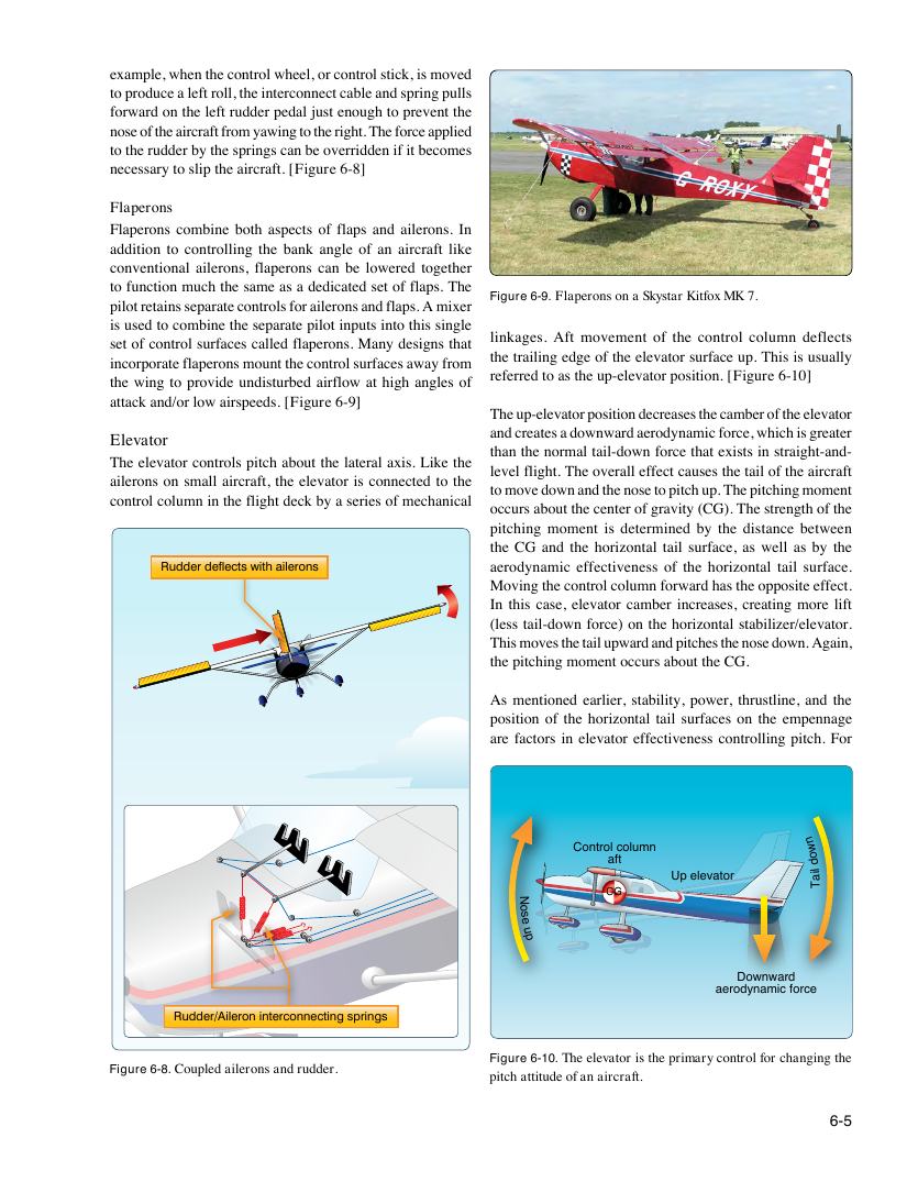
linkages. Aft movement of the control column deflects
set of control surfaces called flaperons. Many designs that
the trailing edge of the elevator surface up. This is usually
incorporate flaperons mount the control surfaces away from
referred to as the up-elevator position. [Figure 6-10]
the wing to provide undisturbed airflow at high angles of
attack and/or low airspeeds. [Figure 6-9]
The up-elevator position decreases the camber of the elevator
and creates a downward aerodynamic force, which is greater
Elevator
than the normal tail-down force that exists in straight-and-
The elevator controls pitch about the lateral axis. Like the
level flight. The overall effect causes the tail of the aircraft
ailerons on small aircraft, the elevator is connected to the
to move down and the nose to pitch up. The pitching moment
control column in the flight deck by a series of mechanical
occurs about the center of gravity (CG). The strength of the
pitching moment is determined by the distance between
the CG and the horizontal tail surface, as well as by the
Rudder deflects with ailerons aerodynamic effectiveness of the horizontal tail surface.
Moving the control column forward has the opposite effect.
In this case, elevator camber increases, creating more lift
(less tail-down force) on the horizontal stabilizer/elevator.
This moves the tail upward and pitches the nose down. Again,
the pitching moment occurs about the CG.
As mentioned earlier, stability, power, thrustline, and the
position of the horizontal tail surfaces on the empennage
are factors in elevator effectiveness controlling pitch. For
Contro
a
l
f
c
t
olumn
n
w
o d
Up elevator lia
T
CG
N
o
s
e
u
p
Downward
aerodynamic force
Rudder/Aileron interconnecting springs
Figure 6-10. The elevator is the primary control for changing the
Figure 6-8. Coupled ailerons and rudder.
pitch attitude of an aircraft.
6-5