FAA-H-8083-25C · Source PDF page 216
Flight Instruments
150 · PHAK page 8-14
Searchable transcription
200 210 220 230 240 250 260 270
58
140
120 70
U
Y
1 1 0 00 2 10 10 6710
30.30
00:03:29 65
U 80
X
V
S 60 10 2320B 10
W
S
40 70
N
E
MA239 5800’
IFR APPR ANG 239 A 239 2.3NM
Figure 8-15. Teledyne’s 90004 TAS/Plus Air Data Computer (ADC)
computes air data information from the pitot-static pneumatic
system, aircraft temperature probe, and barometric correction
device to help create a clear picture of flight characteristics.
does not enter a diaphragm. The ADC computes the received
barometric pressure and sends a digital signal to the PFD to
display the proper altitude readout. EFDs also show trend
vectors, which show the pilot how the altitude and airspeed
are progressing.
Trend Vectors
150
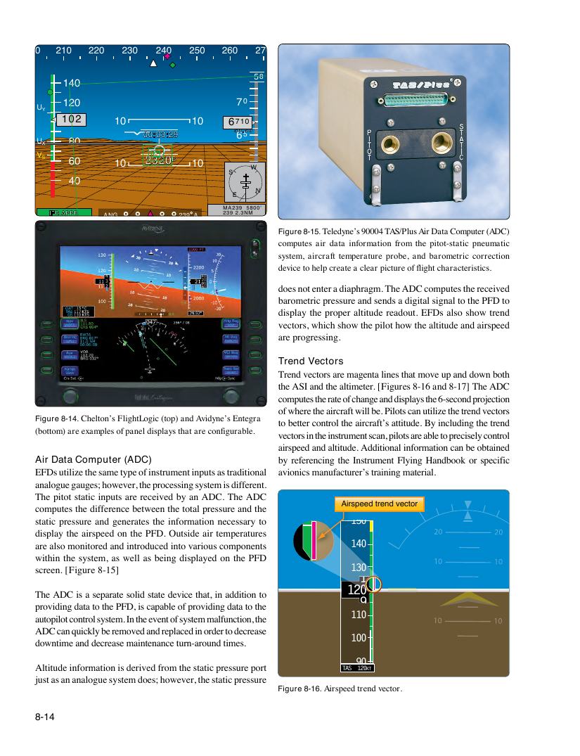
Trend vectors are magenta lines that move up and down both
the ASI and the altimeter. [Figures 8-16 and 8-17] The ADC
computes the rate of change and displays the 6-second projection
of where the aircraft will be. Pilots can utilize the trend vectors
Figure 8-14. Chelton’s FlightLogic (top) and Avidyne’s Entegra to better control the aircraft’s attitude. By including the trend
(bottom) are examples of panel displays that are configurable.140
vectors in the instrument scan, pilots are able to precisely control
airspeed and altitude. Additional information can be obtained
Air Data Computer (ADC) by referencing the Instrument Flying Handbook or specific
EFDs utilize the same type of instrument inputs as traditional avionics manufacturer’s training material.
analogue gauges; however, the processing system is different.
130
The pitot static inputs are received by an ADC. The ADC
Airspeed trend vector
computes the difference between the total pressure and the
1
static pressure and generates the information necessary to 150
display the airspeed on the PFD. Outside air temperatures
are also monitored and introduced into various compo1nent2s 0 140
within the system, as well as being displayed on the PFD
screen. [Figure 8-15] 130
1
9
120
The ADC is a separate solid state device that, in addition to
9
providing data to the PFD, is capable of providing data to the
autopilot control system. In the event of system malfunction, 1the 10 110
ADC can quickly be removed and replaced in order to decrease
100
downtime and decrease maintenance turn-around times.
90
Altitude information is derived from the static pressure port TAS 120KT
just as an analogue system does; however, the static press1ure 00
Figure 8-16. Airspeed trend vector.
8-14
90