FAA-H-8083-25C · Source PDF page 217
Flight Instruments
Precession · PHAK page 8-15
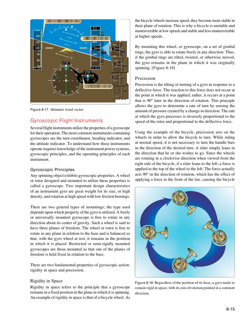
Searchable transcription
the bicycle wheels increase speed, they become more stable in
Airspeed trend (increasing)
their plane of rotation. This is why a bicycle is unstable and
4000
130 4200 maneuverable at low speeds and stable and less maneuverable
2
120 4100 at higher speeds.
Altitude trend vector
110 4000 1
1 40 400045 By mounting this wheel, or gyroscope, on a set of gimbal
100 33909000 3925
9 80 -500 3000 05 -375 rings, the gyro is able to rotate freely in any direction. Thus,
90 3800 1 38 3 0 1 0 00 if the gimbal rings are tilted, twisted, or otherwise moved,
80 270° 3700 2 4 3 00 9 0 5 7 0 0 the gyro remains in the plane in which it was originally
70 3700 390030 -250 spinning. [Figure 8-18]
TAS 100KT 3100
270° 3600
400080
VOR 1 3500 3975 -125 Precession
390070
Turn ra3t4e0 0trend vector
4100 Precession is the tilting or turning of a gyro in response to a
3300 3400000 2 0 0 deflective force. The reaction to this force does not occur at
80 the point at which it was applied; rather, it occurs at a point
3200
3900
that is 90° later in the direction of rotation. This principle
Figure 4-27. Supporting Instruments 3100 allows the gyro to determine a rate of turn by sensing the
Figure 8-17. Altimeter trend vector. amount of pressure created by a change in direction. The rate
at which the gyro precesses is inversely proportional to the
Gyroscopic Flight Instruments speed of the rotor and proportional to the deflective force.
Several flight instruments utilize the properties of a gyroscope
for their operation. The most common instruments containing Using the example of the bicycle, precession acts on the
gyroscopes are the turn coordinator, heading indicator, and wheels in order to allow the bicycle to turn. While riding
the attitude indicator. To understand how these instruments at normal speed, it is not necessary to turn the handle bars
operate requires knowledge of the instrument power systems, in the direction of the desired turn. A rider simply leans in
gyroscopic principles, and the operating principles of each the direction that he or she wishes to go. Since the wheels
instrument. are rotating in a clockwise direction when viewed from the
right side of the bicycle, if a rider leans to the left, a force is
Gyroscopic Principles applied to the top of the wheel to the left. The force actually
Any spinning object exhibits gyroscopic properties. A wheel acts 90° in the direction of rotation, which has the effect of
or rotor designed and mounted to utilize these properties is applying a force to the front of the tire, causing the bicycle
called a gyroscope. Two important design characteristics
of an instrument gyro are great weight for its size, or high
density, and rotation at high speed with low friction bearings.
There are two general types of mountings; the type used
depends upon which property of the gyro is utilized. A freely
or universally mounted gyroscope is free to rotate in any
direction about its center of gravity. Such a wheel is said to
have three planes of freedom. The wheel or rotor is free to
rotate in any plane in relation to the base and is balanced so
that, with the gyro wheel at rest, it remains in the position
in which it is placed. Restricted or semi-rigidly mounted
gyroscopes are those mounted so that one of the planes of
freedom is held fixed in relation to the base.
There are two fundamental properties of gyroscopic action:
rigidity in space and precession.
Rigidity in Space
Figure 8-18. Regardless of the position of its base, a gyro tends to
Rigidity in space refers to the principle that a gyroscope remain rigid in space, with its axis of rotation pointed in a constant
remains in a fixed position in the plane in which it is spinning. direction.
An example of rigidity in space is that of a bicycle wheel. As
8-15