FAA-H-8083-25C · Source PDF page 215
Flight Instruments
Electronic Flight Display (EFD) · PHAK page 8-13
Searchable transcription
normal range, and caution range. [Figure 8-12] The number Turn Indicator
value changes color to red when the airspeed exceeds V NE to The turn indicator takes a slightly different form than the
warn the pilot of exceeding the maximum speed limitation. traditional instrumentation. A sliding bar moves left and right
below the triangle to indicate deflection from coordinated
Attitude Indicator flight. [Figure 8-12] Reference for coordinated flight comes
One improvement over analogue instrumentation is the from accelerometers contained in the AHRS unit.
larger attitude indicator on EFD. The artificial horizon spans
the entire width of the PFD. [Figure 8-12] This expanded Tachometer
instrumentation offers better reference through all phases of The sixth instrument normally associated with the “six pack”
flight and all flight maneuvers. The attitude indicator receives package is the tachometer. This is the only instrument that is
its information from the Attitude Heading and Reference not located on the PFD. The tachometer is normally located
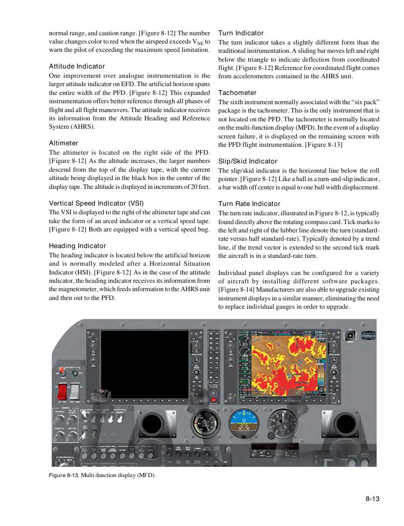
System (AHRS). on the multi-function display (MFD). In the event of a display
screen failure, it is displayed on the remaining screen with
Altimeter the PFD flight instrumentation. [Figure 8-13]
The altimeter is located on the right side of the PFD.
[Figure 8-12] As the altitude increases, the larger numbers Slip/Skid Indicator
descend from the top of the display tape, with the current The slip/skid indicator is the horizontal line below the roll
altitude being displayed in the black box in the center of the pointer. [Figure 8-12] Like a ball in a turn-and-slip indicator,
display tape. The altitude is displayed in increments of 20 feet. a bar width off center is equal to one ball width displacement.
Vertical Speed Indicator (VSI) Turn Rate Indicator
The VSI is displayed to the right of the altimeter tape and can The turn rate indicator, illustrated in Figure 8-12, is typically
take the form of an arced indicator or a vertical speed tape. found directly above the rotating compass card. Tick marks to
[Figure 8-12] Both are equipped with a vertical speed bug. the left and right of the lubber line denote the turn (standard-
rate versus half standard-rate). Typically denoted by a trend
Heading Indicator line, if the trend vector is extended to the second tick mark
The heading indicator is located below the artificial horizon the aircraft is in a standard-rate turn.
and is normally modeled after a Horizontal Situation
Indicator (HSI). [Figure 8-12] As in the case of the attitude Individual panel displays can be configured for a variety
indicator, the heading indicator receives its information from of aircraft by installing different software packages.
the magnetometer, which feeds information to the AHRS unit [Figure 8-14] Manufacturers are also able to upgrade existing
and then out to the PFD. instrument displays in a similar manner, eliminating the need
to replace individual gauges in order to upgrade.
Figure 8-13. Multi-function display (MFD).
8-13