FAA-H-8083-25C · Source PDF page 211
Flight Instruments
Airspeed Indicator Markings · PHAK page 8-9
Searchable transcription
• Calibrated airspeed (CAS)—IAS corrected for
installation error and instrument error. Although
V (red line)
manufacturers attempt to keep airspeed errors to a NE
V
minimum, it is not possible to eliminate all errors S0
Yellow arc
throughout the airspeed operating range. At certain
a a
e
c
a
i n
r
r
r
r
u
r
e
d s
o
i
p
s
a
r
i e
i
n
p
n
e
i
s
p
s
g
d t
r
r s
g
o
u
a
a
e
x
n
m n
n
i
d
m
d e
e
n
r
h
w
a
a
t
i
t
l
i
g
e
t
l
e h
h
y
l
r
y
e
r c o
g
r
e
t
r
r
h
r
a
s
e
t
e
i
a
a
r
m i
t
s
s
n
e
p
a
a
s
f
e
y
m
t
l
e
a
e
a
t
d
p o
.
t
s t
r
R
a
l
e
a
o
l t
n
e
t
w
i s
g
f
n
e
e
e
g
r
v
a
s
s
i
e
,
t
,
r
r
o
s
I
t a h
p
A
l
t
e
e
h
S
k
e
i
e
n n
d
a
s o
s
a
n
t
.
t a
i
d
s
r
l
I
.
s
l
n
a
C
p
T t
e
A
i
t
h o
e
h
i
S
d
n
e
s
041
140
160
F P ° R
A
A 1 E L 2 S
I
K
T
R
0 S
N
S
0 9
O
P
0
T
E
6
S
E
0
D
3 0 5 0
4
- 3
0
0
10
6
1
0
5
20
V S1
calibration chart to correct for possible airspeed errors. V N0 MPH 120 100 HPM White arc
120 120
• True airspeed (TAS)—CAS corrected for altitude 80
and nonstandard temperature. Because air density 10 1 0 00 80 T.A K .S T . S
decreases with an increase in altitude, an aircraft has V
Green arc FE
to be flown faster at higher altitudes to cause the same
pressure difference between pitot impact pressure
and static pressure. Therefore, for a given CAS, TAS
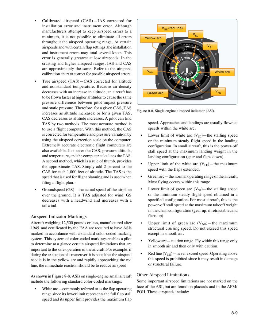
Figure 8-8. Single engine airspeed indicator (ASI).
increases as altitude increases; or for a given TAS,
CAS decreases as altitude increases. A pilot can find
TAS by two methods. The most accurate method is speed. Approaches and landings are usually flown at
to use a flight computer. With this method, the CAS speeds within the white arc.
is corrected for temperature and pressure variation by • Lower limit of white arc (V )—the stalling speed
S0
using the airspeed correction scale on the computer. or the minimum steady flight speed in the landing
Extremely accurate electronic flight computers are configuration. In small aircraft, this is the power-off
also available. Just enter the CAS, pressure altitude, stall speed at the maximum landing weight in the
and temperature, and the computer calculates the TAS. landing configuration (gear and flaps down).
A second method, which is a rule of thumb, provides
• Upper limit of the white arc (V )—the maximum
the approximate TAS. Simply add 2 percent to the FE
speed with the flaps extended.
CAS for each 1,000 feet of altitude. The TAS is the
speed that is used for flight planning and is used when • Green arc—the normal operating range of the aircraft.
filing a flight plan. Most flying occurs within this range.
• Groundspeed (GS)—the actual speed of the airplane • Lower limit of green arc (V S1 )—the stalling speed
over the ground. It is TAS adjusted for wind. GS or the minimum steady flight speed obtained in a
decreases with a headwind and increases with a specified configuration. For most aircraft, this is the
tailwind. power-off stall speed at the maximum takeoff weight
in the clean configuration (gear up, if retractable, and
Airspeed Indicator Markings flaps up).
Aircraft weighing 12,500 pounds or less, manufactured after • Upper limit of green arc (V )—the maximum
N0
1945, and certificated by the FAA are required to have ASIs structural cruising speed. Do not exceed this speed
marked in accordance with a standard color-coded marking except in smooth air.
system. This system of color-coded markings enables a pilot
• Yellow arc—caution range. Fly within this range only
to determine at a glance certain airspeed limitations that are
in smooth air and then only with caution.
important to the safe operation of the aircraft. For example, if
during the execution of a maneuver, it is noted that the airspeed • Red line (V NE )—never exceed speed. Operating above
needle is in the yellow arc and rapidly approaching the red this speed is prohibited since it may result in damage
line, the immediate reaction should be to reduce airspeed. or structural failure.
As shown in Figure 8-8, ASIs on single-engine small aircraft Other Airspeed Limitations
include the following standard color-coded markings: Some important airspeed limitations are not marked on the
face of the ASI, but are found on placards and in the AFM/
• White arc—commonly referred to as the flap operating
POH. These airspeeds include:
range since its lower limit represents the full flap stall
speed and its upper limit provides the maximum flap
8-9