FAA-H-8083-25C · Source PDF page 225
Flight Instruments
Compass Systems · PHAK page 8-23
Searchable transcription
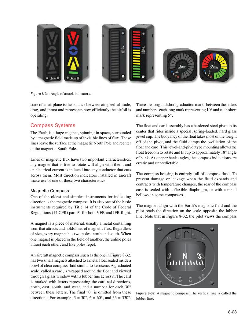
Figure 8-31. Angle of attack indicators.
state of an airplane is the balance between airspeed, altitude, There are long and short graduation marks between the letters
drag, and thrust and represents how efficiently the airfoil is and numbers, each long mark representing 10° and each short
operating. mark representing 5°.
Compass Systems The float and card assembly has a hardened steel pivot in its
center that rides inside a special, spring-loaded, hard glass
The Earth is a huge magnet, spinning in space, surrounded
jewel cup. The buoyancy of the float takes most of the weight
by a magnetic field made up of invisible lines of flux. These
off of the pivot, and the fluid damps the oscillation of the
lines leave the surface at the magnetic North Pole and reenter
float and card. This jewel-and-pivot type mounting allows the
at the magnetic South Pole.
float freedom to rotate and tilt up to approximately 18° angle
of bank. At steeper bank angles, the compass indications are
Lines of magnetic flux have two important characteristics:
erratic and unpredictable.
any magnet that is free to rotate will align with them, and
an electrical current is induced into any conductor that cuts
The compass housing is entirely full of compass fluid. To
across them. Most direction indicators installed in aircraft
prevent damage or leakage when the fluid expands and
make use of one of these two characteristics.
contracts with temperature changes, the rear of the compass
case is sealed with a flexible diaphragm, or with a metal
Magnetic Compass
bellows in some compasses.
One of the oldest and simplest instruments for indicating
direction is the magnetic compass. It is also one of the basic
The magnets align with the Earth’s magnetic field and the
instruments required by Title 14 of the Code of Federal
pilot reads the direction on the scale opposite the lubber
Regulations (14 CFR) part 91 for both VFR and IFR flight.
line. Note that in Figure 8-32, the pilot views the compass
A magnet is a piece of material, usually a metal containing
iron, that attracts and holds lines of magnetic flux. Regardless
of size, every magnet has two poles: north and south. When
one magnet is placed in the field of another, the unlike poles
attract each other, and like poles repel.
An aircraft magnetic compass, such as the one in Figure 8-32,
has two small magnets attached to a metal float sealed inside a
bowl of clear compass fluid similar to kerosene. A graduated
scale, called a card, is wrapped around the float and viewed
through a glass window with a lubber line across it. The card
is marked with letters representing the cardinal directions, N-S E-W
north, east, south, and west, and a number for each 30°
between these letters. The final “0” is omitted from these Figure 8-32. A magnetic compass. The vertical line is called the
directions. For example, 3 = 30°, 6 = 60°, and 33 = 330°. lubber line.
8-23