FAA-H-8083-25C · Source PDF page 224
Flight Instruments
Instrument Check · PHAK page 8-22
Searchable transcription
a signal relayed to the heading indicator unit, which is also or “spills” and no longer gives the correct indication until
remotely mounted. This signal operates a torque motor in reset. After spilling, it may be reset with the caging knob.
the heading indicator unit that processes the gyro unit until Many of the modern instruments used are designed in such
it is aligned with the transmitter signal. The magnetic slaving a manner so that they do not tumble.
transmitter is connected electrically to the HSI.
An additional precession error may occur due to a gyro not
There are a number of designs of the remote indicating spinning fast enough to maintain its alignment. When the
compass; therefore, only the basic features of the system are vacuum system stops producing adequate suction to maintain
covered here. Instrument pilots must become familiar with the gyro speed, the heading indicator and the attitude indicator
the characteristics of the equipment in their aircraft. gyros begin to slow down. As they slow, they become more
susceptible to deflection from the plane of rotation. Some
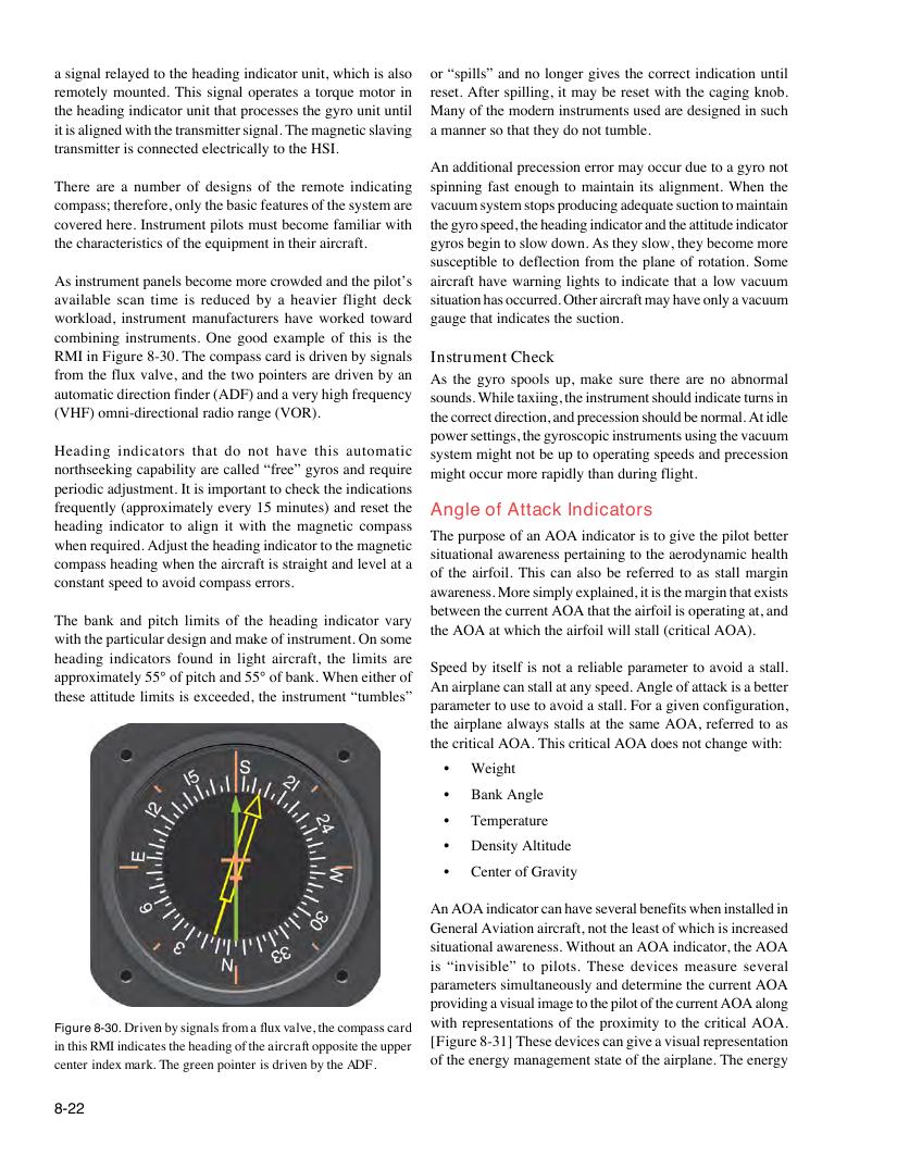
As instrument panels become more crowded and the pilot’s aircraft have warning lights to indicate that a low vacuum
available scan time is reduced by a heavier flight deck situation has occurred. Other aircraft may have only a vacuum
workload, instrument manufacturers have worked toward gauge that indicates the suction.
combining instruments. One good example of this is the
RMI in Figure 8-30. The compass card is driven by signals Instrument Check
from the flux valve, and the two pointers are driven by an As the gyro spools up, make sure there are no abnormal
automatic direction finder (ADF) and a very high frequency sounds. While taxiing, the instrument should indicate turns in
(VHF) omni-directional radio range (VOR). the correct direction, and precession should be normal. At idle
power settings, the gyroscopic instruments using the vacuum
Heading indicators that do not have this automatic system might not be up to operating speeds and precession
northseeking capability are called “free” gyros and require might occur more rapidly than during flight.
periodic adjustment. It is important to check the indications
frequently (approximately every 15 minutes) and reset the Angle of Attack Indicators
heading indicator to align it with the magnetic compass
The purpose of an AOA indicator is to give the pilot better
when required. Adjust the heading indicator to the magnetic
situational awareness pertaining to the aerodynamic health
compass heading when the aircraft is straight and level at a
of the airfoil. This can also be referred to as stall margin
constant speed to avoid compass errors.
awareness. More simply explained, it is the margin that exists
between the current AOA that the airfoil is operating at, and
The bank and pitch limits of the heading indicator vary
the AOA at which the airfoil will stall (critical AOA).
with the particular design and make of instrument. On some
heading indicators found in light aircraft, the limits are
Speed by itself is not a reliable parameter to avoid a stall.
approximately 55° of pitch and 55° of bank. When either of
An airplane can stall at any speed. Angle of attack is a better
these attitude limits is exceeded, the instrument “tumbles”
parameter to use to avoid a stall. For a given configuration,
the airplane always stalls at the same AOA, referred to as
the critical AOA. This critical AOA does not change with:
• Weight
• Bank Angle
• Temperature
• Density Altitude
• Center of Gravity
An AOA indicator can have several benefits when installed in
General Aviation aircraft, not the least of which is increased
situational awareness. Without an AOA indicator, the AOA
is “invisible” to pilots. These devices measure several
parameters simultaneously and determine the current AOA
providing a visual image to the pilot of the current AOA along
with representations of the proximity to the critical AOA.
Figure 8-30. Driven by signals from a flux valve, the compass card
[Figure 8-31] These devices can give a visual representation
in this RMI indicates the heading of the aircraft opposite the upper
of the energy management state of the airplane. The energy
center index mark. The green pointer is driven by the ADF.
8-22