FAA-H-8083-25C · Source PDF page 214
Flight Instruments
Electronic Flight Display (EFD) · PHAK page 8-12
Searchable transcription
available to a pilot, but also how the information is displayed.
Inaccurate airspeed indications In addition to the improvement in system reliability, which
increases overall safety, EFDs have decreased the overall cost
Constant zero indication on VSI of equipping aircraft with state-of-the-art instrumentation.
Primary electronic instrumentation packages are less prone
Frozen altimeter to failure than their analogue counterparts. No longer is it
necessary for aircraft designers to create cluttered panel
layouts in order to accommodate all necessary flight
2 329 09. ..8 09 instruments. Instead, multi-panel digital flight displays
combine all flight instruments onto a single screen that is
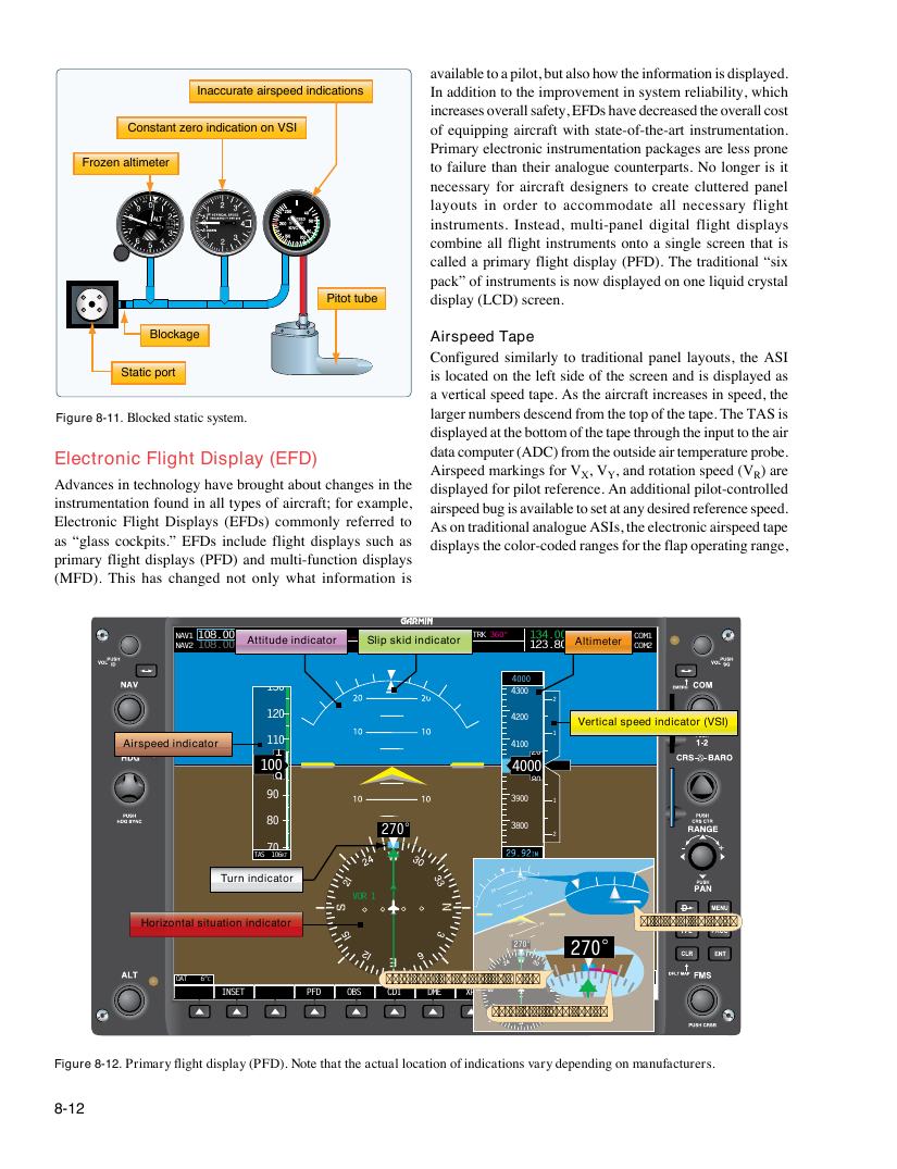
called a primary flight display (PFD). The traditional “six
pack” of instruments is now displayed on one liquid crystal
Pitot tube display (LCD) screen.
Blockage Airspeed Tape
Configured similarly to traditional panel layouts, the ASI
Static port is located on the left side of the screen and is displayed as
a vertical speed tape. As the aircraft increases in speed, the
larger numbers descend from the top of the tape. The TAS is
Figure 8-11. Blocked static system.
displayed at the bottom of the tape through the input to the air
data computer (ADC) from the outside air temperature probe.
Electronic Flight Display (EFD)
Airspeed markings for V , V , and rotation speed (V ) are
X Y R
Advances in technology have brought about changes in the
displayed for pilot reference. An additional pilot-controlled
instrumentation found in all types of aircraft; for example,
airspeed bug is available to set at any desired reference speed.
Electronic Flight Displays (EFDs) commonly referred to
As on traditional analogue ASIs, the electronic airspeed tape
as “glass cockpits.” EFDs include flight displays such as
displays the color-coded ranges for the flap operating range,
primary flight displays (PFD) and multi-function displays
(MFD). This has changed not only what information is
NAV1 108.00 113.00 WPT _ _ _ _ _ _ DIS _ _ ._ NM DTK _ _ _°T TRK 360° 134.000 118.000 COM1
NAV2 108.00 A11tt0it.u6d0e indicator Slip skid indicator 123.800 A l1ti1m8e.t0e0r0 COM2
4000
130
4300
2
120
4200
Vertical speed indicator (VSI)
1
110
Airspeed indicator 1 4100 20
100 4000
3900
9 80
90
3900 1
80
270° 3800
2
70
TAS 106KT 4300
Turn indicator 3600
VOR 1
3500
Horizontal situation indicator Slip/skid indicator
3400
270° 270°
3300
OAT 6°C
INSET PFD OBS
T
C
u
DI
rn rate
D M
i
E
ndica
X
to
PD
r
R
tick
V I O
m
R D 31 E
a
2
X
N0
rP
T0
kDRs
T M
5
R
5
/
3
R
7
E F
IDN
N
T
R S T
LCL10
A
:
L
1
E
2
R
:
T
3
S
4
Turn3 1r0a0te trend vector
Figure 8-12. Primary flight display (PFD). Note that the actual location of indications vary depending on manufacturers.
8-12