FAA-H-8083-25C · Source PDF page 220
Flight Instruments
Instrument Check · PHAK page 8-18
Searchable transcription
to the center of the wind screen. When in coordinated flight,
the string trails straight back over the top of the wind screen.
E D L . E C C . . E D L . E C C . . When the aircraft is either slipping or skidding, the yaw
string moves to the right or left depending on the direction
of slip or skid.
TURN COORDINATOR TURN COORDINATOR
L R L R
2 MIN. 2 MIN. Instrument Check
NO PITCH NO PITCH
INFORMATION INFORMATION
During preflight, ensure that the inclinometer is full of fluid
and has no air bubbles. The ball should also be resting at
Slipping turn Skidding turn
its lowest point. When taxiing, the turn coordinator should
indicate a turn in the correct direction while the ball moves
D.C. opposite the direction of the turn.
ELEC.
Attitude Indicator
TURN COORDINATOR The attitude indicator, with its miniature aircraft and horizon
L R bar, displays a picture of the attitude of the aircraft. The
2 MIN.
IN N FO O R P M I A TC TI H ON relationship of the miniature aircraft to the horizon bar is
the same as the relationship of the real aircraft to the actual
Coordinated turn horizon. The instrument gives an instantaneous indication of
even the smallest changes in attitude.
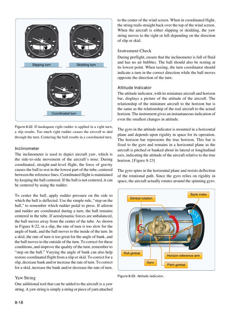
Figure 8-22. If inadequate right rudder is applied in a right turn,
The gyro in the attitude indicator is mounted in a horizontal
a slip results. Too much right rudder causes the aircraft to skid
plane and depends upon rigidity in space for its operation.
through the turn. Centering the ball results in a coordinated turn.
The horizon bar represents the true horizon. This bar is
fixed to the gyro and remains in a horizontal plane as the
Inclinometer aircraft is pitched or banked about its lateral or longitudinal
The inclinometer is used to depict aircraft yaw, which is axis, indicating the attitude of the aircraft relative to the true
the side-to-side movement of the aircraft’s nose. During horizon. [Figure 8-23]
coordinated, straight-and-level flight, the force of gravity
causes the ball to rest in the lowest part of the tube, centered The gyro spins in the horizontal plane and resists deflection
between the reference lines. Coordinated flight is maintained of the rotational path. Since the gyro relies on rigidity in
by keeping the ball centered. If the ball is not centered, it can space, the aircraft actually rotates around the spinning gyro.
be centered by using the rudder.
To center the ball, apply rudder pressure on the side to Bank index
Gimbal rotation
which the ball is deflected. Use the simple rule, “step on the
ball,” to remember which rudder pedal to press. If aileron
and rudder are coordinated during a turn, the ball remains
centered in the tube. If aerodynamic forces are unbalanced,
t
i
h
n
e
F
b
ig
al
u
l
r
m
e
o
8
v
-2
e
2
s
,
a
i
w
n
a
a
y
s
f
l
r
ip
o
,
m
th
t
e
h e
r a
c
t
e
e
n
o
te
f
r
t u
o
r
f
n
t h
is
e
t
t
o
u
o
b e
s
.
l o
A
w
s
f
s
o
h
r
o w
th
n
e
20
I 0
I 02
2
0
0
I 0
I 0
20
a
a
n
s
g
k
l
i
e
d ,
o
t
f
h
b
e
a
r
n
a
k
te
, a
o
n
f
d
t u
th
rn
e b
is
a
t
l
o
l m
o g
o
r
v
e
e
a
s
t
t
f
o
o
t
r
h
t
e
h e
in
a
s
n
id
g
e
le
o
o
f
f
t h
b
e
a n
tu
k
r
,
n
a
.
n
I
d
n
20
I 0 I 0
2 0
2I 0 0 I 0 20
the ball moves to the outside of the turn. To correct for these TEST
STBY PWR
conditions, and improve the quality of the turn, remember to
“step on the ball.” Varying the angle of bank can also help
Roll gimbal
restore coordinated flight from a slip or skid. To correct for a Horizon reference arm
slip, decrease bank and/or increase the rate of turn. To correct Gyro
Pitch gimbal
for a skid, increase the bank and/or decrease the rate of turn.
Yaw String Figure 8-23. Attitude indicator.
One additional tool that can be added to the aircraft is a yaw
string. A yaw string is simply a string or piece of yarn attached
8-18