FAA-H-8083-25C · Source PDF page 219
Flight Instruments
Turn Coordinator · PHAK page 8-17
Searchable transcription
Heading indicator Vacuum relief valve
33 3
3 0 6
Overboard vent line
4 2 2I
I2 5I
Vacuum pump
20 20
I0 I0
I0 I0
20 20
STBY PWR TEST
4 6
SUCTION
2 8
INCHES MERCURT
0 I0 Suction Attitude indicator
gauge
Vacuum air filter
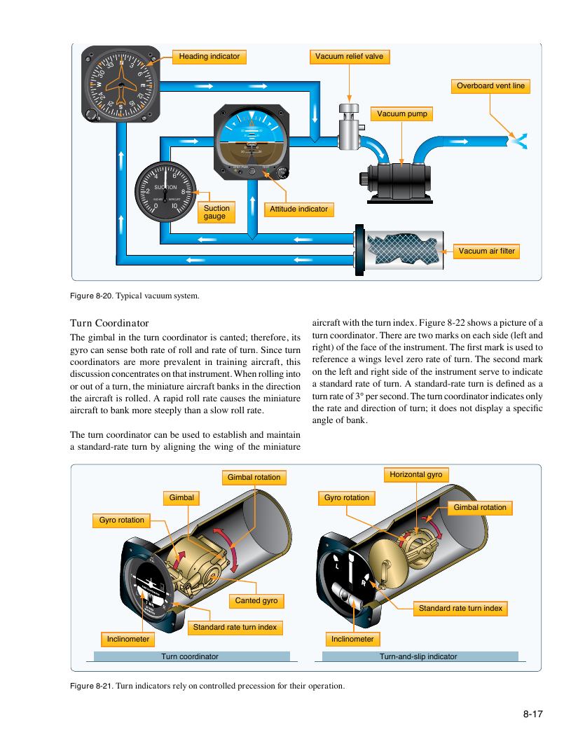
Figure 8-20. Typical vacuum system.
Turn Coordinator aircraft with the turn index. Figure 8-22 shows a picture of a
The gimbal in the turn coordinator is canted; therefore, its turn coordinator. There are two marks on each side (left and
gyro can sense both rate of roll and rate of turn. Since turn right) of the face of the instrument. The first mark is used to
coordinators are more prevalent in training aircraft, this reference a wings level zero rate of turn. The second mark
discussion concentrates on that instrument. When rolling into on the left and right side of the instrument serve to indicate
or out of a turn, the miniature aircraft banks in the direction a standard rate of turn. A standard-rate turn is defined as a
the aircraft is rolled. A rapid roll rate causes the miniature turn rate of 3° per second. The turn coordinator indicates only
aircraft to bank more steeply than a slow roll rate. the rate and direction of turn; it does not display a specific
angle of bank.
The turn coordinator can be used to establish and maintain
a standard-rate turn by aligning the wing of the miniature
Gimbal rotation Horizontal gyro
Gimbal Gyro rotation
Gimbal rotation
Gyro rotation
Canted gyro
Standard rate turn index
Standard rate turn index
Inclinometer Inclinometer
Turn coordinator Turn-and-slip indicator
Figure 8-21. Turn indicators rely on controlled precession for their operation.
8-17