FAA-H-8083-25C · Source PDF page 221
Flight Instruments
Instrument Check · PHAK page 8-19
Searchable transcription
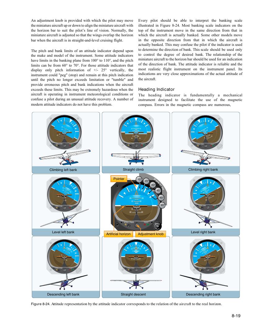
An adjustment knob is provided with which the pilot may move Every pilot should be able to interpret the banking scale
the miniature aircraft up or down to align the miniature aircraft with illustrated in Figure 8-24. Most banking scale indicators on the
the horizon bar to suit the pilot’s line of vision. Normally, the top of the instrument move in the same direction from that in
miniature aircraft is adjusted so that the wings overlap the horizon which the aircraft is actually banked. Some other models move
bar when the aircraft is in straight-and-level cruising flight. in the opposite direction from that in which the aircraft is
actually banked. This may confuse the pilot if the indicator is used
The pitch and bank limits of an attitude indicator depend upon to determine the direction of bank. This scale should be used only
the make and model of the instrument. Some attitude indicators to control the degree of desired bank. The relationship of the
have limits in the banking plane from 100° to 110°, and the pitch miniature aircraft to the horizon bar should be used for an indication
limits can be from 60° to 70°. For those attitude indicators that of the direction of bank. The attitude indicator is reliable and the
display only pitch information of +/- 25° vertically, the most realistic flight instrument on the instrument panel. Its
instrument could "peg" (stop) and remain at this pitch indication indications are very close approximations of the actual attitude of
until the pitch no longer exceeds limitation or "tumble" and the aircraft.
provide erroneous pitch and bank indications when the aircraft
exceeds these limits. This may be extremely hazardous when the Heading Indicator
aircraft is operating in instrument meteorological conditions or The heading indicator is fundamentally a mechanical
confuse a pilot during an unusual attitude recovery. A number of instrument designed to facilitate the use of the magnetic
modern attitude indicators do not have this problem. compass. Errors in the magnetic compass are numerous,
20 I0 2 I0 0 I 2 0 0 I0 20 2 2 0 0 I I 0 0 I 0 I 0 2 2 0 0 20 I0 2 I0 0 2 I0 0 I0 20
STBY PWR TEST STBY PWR TEST STBY PWR TEST
Climbing left bank Straight climb Climbing right bank
Pointer 10° 20°
3 0
B
°
ank
sc
2
I0
0
I0 20 45°
a le
20 I0
2
I0
0
20 I0 I
2
0
0
20
I0 I0
20 60°
2
I0
0
I0 20
STBY PWR TEST 90° STBY PWR TEST
I0 I0
20 20
STBY PWR TEST
Level left bank Level right bank
Artificial horizon Adjustment knob
2 I0 0 I0 20 20 I 0 I 0 20 20 I0 2 I0 0
20 I0 I 2 0 0 20 I 0 I 0 20 2 I0 0 I0 20
STBY PWR TEST STBY PWR TEST STBY PWR TEST
Descending left bank Straight descent Descending right bank
Figure 8-24. Attitude representation by the attitude indicator corresponds to the relation of the aircraft to the real horizon.
8-19