FAA-H-8083-25C · Source PDF page 222
Flight Instruments
Instrument Check · PHAK page 8-20
Searchable transcription
making straight flight and precision turns to headings difficult Attitude and Heading Reference System (AHRS)
to accomplish, particularly in turbulent air. A heading Electronic flight displays have replaced free-spinning gyros
indicator, however, is not affected by the forces that make with solid-state laser systems that are capable of flight at
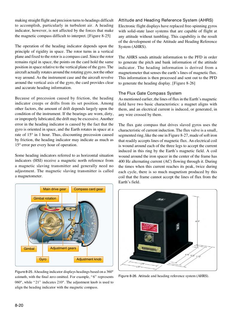
the magnetic compass difficult to interpret. [Figure 8-25] any attitude without tumbling. This capability is the result
of the development of the Attitude and Heading Reference
The operation of the heading indicator depends upon the System (AHRS).
principle of rigidity in space. The rotor turns in a vertical
plane and fixed to the rotor is a compass card. Since the rotor The AHRS sends attitude information to the PFD in order
remains rigid in space, the points on the card hold the same to generate the pitch and bank information of the attitude
position in space relative to the vertical plane of the gyro. The indicator. The heading information is derived from a
aircraft actually rotates around the rotating gyro, not the other magnetometer that senses the earth’s lines of magnetic flux.
way around. As the instrument case and the aircraft revolve This information is then processed and sent out to the PFD
around the vertical axis of the gyro, the card provides clear to generate the heading display. [Figure 8-26]
and accurate heading information.
The Flux Gate Compass System
Because of precession caused by friction, the heading As mentioned earlier, the lines of flux in the Earth’s magnetic
indicator creeps or drifts from its set position. Among field have two basic characteristics: a magnet aligns with
other factors, the amount of drift depends largely upon the them, and an electrical current is induced, or generated, in
condition of the instrument. If the bearings are worn, dirty, any wire crossed by them.
or improperly lubricated, the drift may be excessive. Another
error in the heading indicator is caused by the fact that the The flux gate compass that drives slaved gyros uses the
gyro is oriented in space, and the Earth rotates in space at a characteristic of current induction. The flux valve is a small,
rate of 15° in 1 hour. Thus, discounting precession caused segmented ring, like the one in Figure 8-27, made of soft iron
by friction, the heading indicator may indicate as much as that readily accepts lines of magnetic flux. An electrical coil
15° error per every hour of operation. is wound around each of the three legs to accept the current
induced in this ring by the Earth’s magnetic field. A coil
Some heading indicators referred to as horizontal situation wound around the iron spacer in the center of the frame has
indicators (HSI) receive a magnetic north reference from 400 Hz alternating current (AC) flowing through it. During
a magnetic slaving transmitter and generally need no the times when this current reaches its peak, twice during
adjustment. The magnetic slaving transmitter is called each cycle, there is so much magnetism produced by this
a magnetometer. coil that the frame cannot accept the lines of flux from the
Earth’s field.
Main drive gear Compass card gear
Gimbal rotation
33 3
3 0 6
4
2
2I
I2 5I
Gimbal Adjustment gears
Gyro Adjustment knob
Figure 8-25. A heading indicator displays headings based on a 360°
azimuth, with the final zero omitted. For example, “6” represents Figure 8-26. Attitude and heading reference system (AHRS).
060°, while “21” indicates 210°. The adjustment knob is used to
align the heading indicator with the magnetic compass.
8-20