FAA-H-8083-25C · Source PDF page 223
Flight Instruments
Instrument Check · PHAK page 8-21
Searchable transcription
Remote Indicating Compass
Remote indicating compasses were developed to compensate
for the errors and limitations of the older type of heading
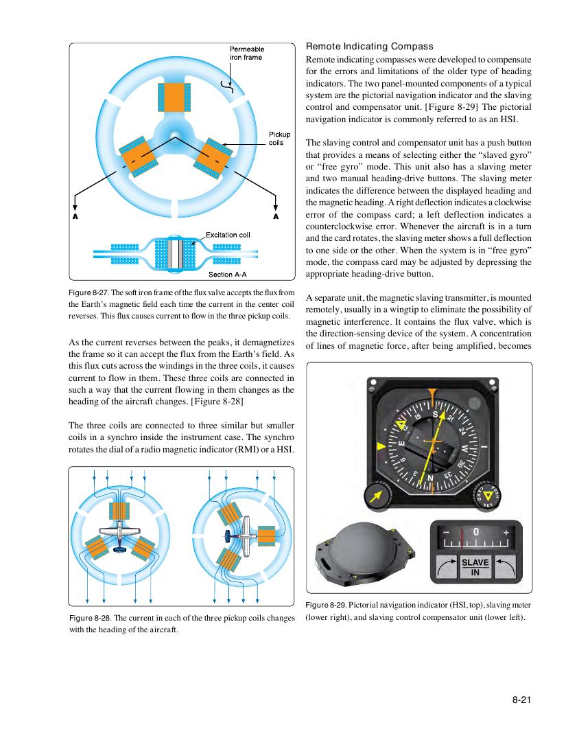
indicators. The two panel-mounted components of a typical
system are the pictorial navigation indicator and the slaving
control and compensator unit. [Figure 8-29] The pictorial
navigation indicator is commonly referred to as an HSI.
The slaving control and compensator unit has a push button
that provides a means of selecting either the “slaved gyro”
or “free gyro” mode. This unit also has a slaving meter
and two manual heading-drive buttons. The slaving meter
indicates the difference between the displayed heading and
the magnetic heading. A right deflection indicates a clockwise
error of the compass card; a left deflection indicates a
counterclockwise error. Whenever the aircraft is in a turn
and the card rotates, the slaving meter shows a full deflection
to one side or the other. When the system is in “free gyro”
mode, the compass card may be adjusted by depressing the
appropriate heading-drive button.
Figure 8-27. The soft iron frame of the flux valve accepts the flux from
A separate unit, the magnetic slaving transmitter, is mounted
the Earth’s magnetic field each time the current in the center coil
Figure 3-23. The soft iron frame of the flux valve accepts the remotely, usually in a wingtip to eliminate the possibility of
reversfleusx. fTrohmis ftlhuex E caaruths’ess m caugrrneentitc t foie flldo wea icnh tthime eth trheee c puircrkeunpt icno tihlse. magnetic interference. It contains the flux valve, which is
center coil reverse. This flux causes current to flow in the three
the direction-sensing device of the system. A concentration
picked coils.
As the current reverses between the peaks, it demagnetizes
of lines of magnetic force, after being amplified, becomes
the frame so it can accept the flux from the Earth’s field. As
this flux cuts across the windings in the three coils, it causes
current to flow in them. These three coils are connected in
such a way that the current flowing in them changes as the
heading of the aircraft changes. [Figure 8-28]
The three coils are connected to three similar but smaller
coils in a synchro inside the instrument case. The synchro
rotates the dial of a radio magnetic indicator (RMI) or a HSI.
Figure 8-29. Pictorial navigation indicator (HSI, top), slaving meter
Figure 8-28. The current in each of the three pickup coils changes (lower right), and slaving control compensator unit (lower left).
with the heading of the aircraft.
Figure 3-24. The current in each of the three pickup coils
changes with the heading of the aircraft.
8-21