FAA-H-8083-25C · Source PDF page 218
Flight Instruments
Turn-and-Slip Indicator · PHAK page 8-16
Searchable transcription
Plane
of
Precession
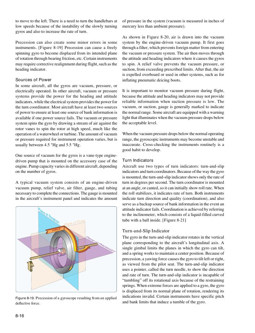
Figure 8-19. Precession of a gyroscope resulting from an applied
deflective force.
8-16
P al n e o f F o r c e
Plane
of
Rotation
F O R C E
to move to the left. There is a need to turn the handlebars at of pressure in the system (vacuum is measured in inches of
low speeds because of the instability of the slowly turning mercury less than ambient pressure).
gyros and also to increase the rate of turn.
As shown in Figure 8-20, air is drawn into the vacuum
Precession can also create some minor errors in some system by the engine-driven vacuum pump. It first goes
instruments. [Figure 8-19] Precession can cause a freely through a filter, which prevents foreign matter from entering
spinning gyro to become displaced from its intended plane the vacuum or pressure system. The air then moves through
of rotation through bearing friction, etc. Certain instruments the attitude and heading indicators where it causes the gyros
may require corrective realignment during flight, such as the to spin. A relief valve prevents the vacuum pressure, or
heading indicator. suction, from exceeding prescribed limits. After that, the air
is expelled overboard or used in other systems, such as for
Sources of Power inflating pneumatic deicing boots.
In some aircraft, all the gyros are vacuum, pressure, or
electrically operated. In other aircraft, vacuum or pressure It is important to monitor vacuum pressure during flight,
systems provide the power for the heading and attitude because the attitude and heading indicators may not provide
indicators, while the electrical system provides the power for reliable information when suction pressure is low. The
the turn coordinator. Most aircraft have at least two sources vacuum, or suction, gauge is generally marked to indicate
of power to ensure at least one source of bank information is the normal range. Some aircraft are equipped with a warning
available if one power source fails. The vacuum or pressure light that illuminates when the vacuum pressure drops below
system spins the gyro by drawing a stream of air against the the acceptable level.
rotor vanes to spin the rotor at high speed, much like the
operation of a waterwheel or turbine. The amount of vacuum When the vacuum pressure drops below the normal operating
or pressure required for instrument operation varies, but is range, the gyroscopic instruments may become unstable and
usually between 4.5 "Hg and 5.5 "Hg. inaccurate. Cross-checking the instruments routinely is a
good habit to develop.
One source of vacuum for the gyros is a vane-type engine-
driven pump that is mounted on the accessory case of the Turn Indicators
engine. Pump capacity varies in different aircraft, depending Aircraft use two types of turn indicators: turn-and-slip
on the number of gyros. indicators and turn coordinators. Because of the way the gyro
is mounted, the turn-and-slip indicator shows only the rate of
A typical vacuum system consists of an engine-driven turn in degrees per second. The turn coordinator is mounted
vacuum pump, relief valve, air filter, gauge, and tubing at an angle, or canted, so it can initially show roll rate. When
necessary to complete the connections. The gauge is mounted the roll stabilizes, it indicates rate of turn. Both instruments
in the aircraft’s instrument panel and indicates the amount indicate turn direction and quality (coordination), and also
serve as a backup source of bank information in the event an
attitude indicator fails. Coordination is achieved by referring
to the inclinometer, which consists of a liquid-filled curved
tube with a ball inside. [Figure 8-21]
Turn-and-Slip Indicator
The gyro in the turn-and-slip indicator rotates in the vertical
plane corresponding to the aircraft’s longitudinal axis. A
single gimbal limits the planes in which the gyro can tilt,
and a spring works to maintain a center position. Because of
precession, a yawing force causes the gyro to tilt left or right,
as viewed from the pilot seat. The turn-and-slip indicator
uses a pointer, called the turn needle, to show the direction
and rate of turn. The turn-and-slip indicator is incapable of
“tumbling” off its rotational axis because of the restraining
springs. When extreme forces are applied to a gyro, the gyro
is displaced from its normal plane of rotation, rendering its
indications invalid. Certain instruments have specific pitch
and bank limits that induce a tumble of the gyro.