FAA-H-8083-25C · Source PDF page 407
Navigation
Charting the Course · PHAK page 16-20
Searchable transcription
PILOT’S PLANNING SHEET
PLANE IDENTIFICATION N123DB DATE
WIND WCA MAG VAR TOTAL TOTAL FUEL TOTAL
COURSE TC ALTITUDE TH MH DEV CH GS
Knots From R+ L- W+ E- MILES TIME RATE FUEL
Fro m Chickasha
031° 10 360° 8000 3° L 28 7° E 21° +2° 23 53 106 kts 35 min 8 GPH 38 gal
To Guthrie
From
To
VISUAL FLIGHT LOG
TIME OF NAVIGATION
COURSE ALTITUDE DISTANCE ELAPSED TIME GS CH REMARKS
DEPARTURE AIDS
Ch D ic E P k P O a A s IN h R T a T O A U i R F rp E ort N I F D A R E V E N A Q T ID . . TO FROM TO FROM POINT T C O U P M O U IN LA T TIVE ESTIMA A T C E T D UAL ESTIM AC A T TE U D AL ESTIM AC A T TE U D AL AIR W S E P A A T C H E E E R TC.
CHECKPOINT 8000 11 NM 6 min 106 kts 023°
#1 10000 +5
CHECKPOINT 8000 10 NM 6 min 106 kts 023°
#2 10000 21 NM
CHECKPOINT 8000 10.5 NM 6 min 106 kts 023°
#3 10000 31.5 NM
CHECKPOINT 8000 13 NM 7 min 106 kts 023°
#4 10000 44.5 NM
DESTINATION 8.5 NM 5 min
Guthrie Airport 53 NM
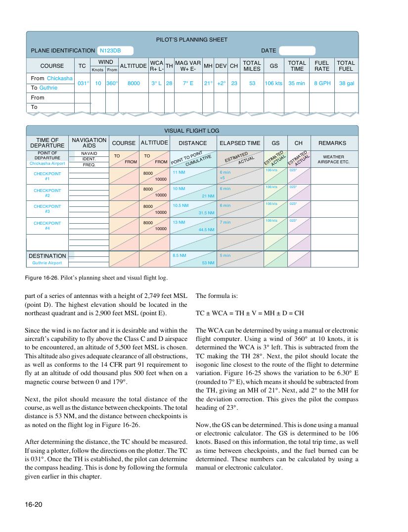
Figure 16-26. Pilot’s planning sheet and visual flight log.
part of a series of antennas with a height of 2,749 feet MSL The formula is:
(point D). The highest elevation should be located in the
northeast quadrant and is 2,900 feet MSL (point E). TC ± WCA = TH ± V = MH ± D = CH
Since the wind is no factor and it is desirable and within the The WCA can be determined by using a manual or electronic
aircraft’s capability to fly above the Class C and D airspace flight computer. Using a wind of 360° at 10 knots, it is
to be encountered, an altitude of 5,500 feet MSL is chosen. determined the WCA is 3° left. This is subtracted from the
This altitude also gives adequate clearance of all obstructions, TC making the TH 28°. Next, the pilot should locate the
as well as conforms to the 14 CFR part 91 requirement to isogonic line closest to the route of the flight to determine
fly at an altitude of odd thousand plus 500 feet when on a variation. Figure 16-25 shows the variation to be 6.30° E
magnetic course between 0 and 179°. (rounded to 7° E), which means it should be subtracted from
the TH, giving an MH of 21°. Next, add 2° to the MH for
Next, the pilot should measure the total distance of the the deviation correction. This gives the pilot the compass
course, as well as the distance between checkpoints. The total heading of 23°.
distance is 53 NM, and the distance between checkpoints is
as noted on the flight log in Figure 16-26. Now, the GS can be determined. This is done using a manual
or electronic calculator. The GS is determined to be 106
After determining the distance, the TC should be measured. knots. Based on this information, the total trip time, as well
If using a plotter, follow the directions on the plotter. The TC as time between checkpoints, and the fuel burned can be
is 031°. Once the TH is established, the pilot can determine determined. These numbers can be calculated by using a
the compass heading. This is done by following the formula manual or electronic calculator.
given earlier in this chapter.
16-20